NOTE
Syncfusion® recommends using Blazor Diagram Component which provides better performance than this diagram control. Blazor Diagram Component will be actively developed in the future.
Positioning in Blazor Diagram Component
27 Oct 20255 minutes to read
Arrange the nodes
-
Position of a node is controlled by using the OffsetX and OffsetY properties. By default, these offset properties represent the distance between the origin of the diagram’s page and node’s center point.
-
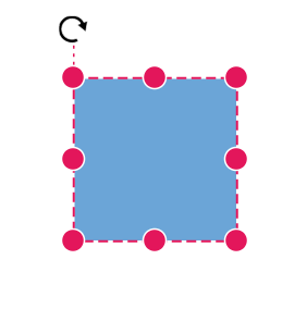
You may expect this offset values to represent the distance between page origin and node’s top-left corner instead of center. The Pivot property helps to solve this problem. Default value of node’s Pivot point is (0.5, 0.5) that means center of the node.
-
The size of the node can be controlled by using the Width and Height properties.
-
Rotation of a node is controlled by using the RotateAngle property.
The following table shows how pivot relates offset values with node boundaries.
| Pivot | Offset |
|---|---|
| (0.5,0.5) | OffsetX and OffsetY values are considered as the node’s center point. |
| (0,0) | OffsetX and OffsetY values are considered as the top-left corner of the node. |
| (1,1) | OffsetX and OffsetY values are considered as the bottom-right corner of the node. |
The following code shows how to change the Pivot value.
@using Syncfusion.Blazor.Diagrams
@using System.Collections.ObjectModel

<SfDiagram Height="600px" @ref="@diagram" Nodes="@NodeCollection">
</SfDiagram>

@code {
    SfDiagram diagram;
    public ObservableCollection<DiagramNode> NodeCollection = new ObservableCollection<DiagramNode>() { };
    protected override void OnInitialized()
    {
        // A node is created and stored in nodes array.
        DiagramNode node1 = new DiagramNode()
        {
            // Position of the node
            OffsetX = 250,
            OffsetY = 250,
            // Size of the node
            Width = 100,
            Height = 100,
            Style = new NodeShapeStyle() { Fill = "#6BA5D7", StrokeColor = "white" },
            // Pivot of the node
            Pivot = new NodePivotPoint() { X = 0, Y = 0 }
        };
        NodeCollection.Add(node1);
    }

    protected override async Task OnAfterRenderAsync(bool firstRender)
    {
        if (firstRender)
        {
            //OnAfterRenderAsync will be triggered after the component rendered.
            await Task.Delay(1500);
            diagram.Select(new ObservableCollection<DiagramNode>() { diagram.Nodes[0] }, null);
        }
    }
}
Flip
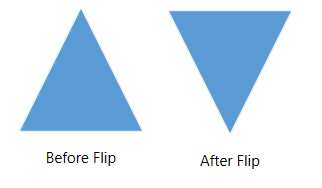
The diagram Provides support to flip the node. Flip is performed to give the mirrored image of the original element.
The flip types are as follows:
-
HorizontalFlipis used to change the element in the horizontal direction. -
VerticalFlipis used to change the element in the vertical direction -
Boththat involves both vertical and horizontal changes of the element.
The following code shows how to provide the mirror image of the original element.
@using Syncfusion.Blazor.Diagrams
@using System.Collections.ObjectModel

<SfDiagram Height="600px" Nodes="@NodeCollection">
</SfDiagram>

@code {
    SfDiagram diagram;
    public ObservableCollection<DiagramNode> NodeCollection = new ObservableCollection<DiagramNode>() { };
    protected override void OnInitialized()
    {
        // A node is created and stored in nodes array.
        DiagramNode node1 = new DiagramNode()
        {
            // Position of the node
            OffsetX = 250,
            OffsetY = 250,
            // Size of the node
            Width = 100,
            Height = 100,
            Style = new NodeShapeStyle() { Fill = "#6BA5D7", StrokeColor = "white" },
            // Flip the node in Vertical Direction
            Flip = FlipDirection.Vertical,
            Shape = new DiagramShape()
            {
                Type = Syncfusion.Blazor.Diagrams.Shapes.Basic,
                BasicShape = BasicShapes.Triangle
            }
        };
        // Add node
        NodeCollection.Add(node1);
    }
}
NOTE
The flip is also applicable for group and BPMN shapes.