How can I help you?
Node Annotation Position in Blazor Diagram Component
2 Feb 202613 minutes to read
The diagram allows you to customize the position and appearance of the annotation efficiently. Annotations can be aligned relative to the node boundaries. It has margin, offset, horizontal, and vertical alignment settings. It is quite tricky when all four alignments are used together but gives more control over alignments properties of the ShapeAnnotation class.
Annotations of a node can be positioned using the following properties of ShapeAnnotation.
- Offset
- HorizontalAlignment
- VerticalAlignment
- Margin
How to Change Annotation Offset Position
The Offset property of an annotation is used to align the annotations based on fractions. It is defined by a DiagramPoint where the X and Y values are fractions of the node’s width and height, respectively. A value of 0 represents the top or left edge, 1 represents the bottom or right edge, and 0.5 represents the center.
The following code demonstrates how to set an annotation’s Offset.
@using Syncfusion.Blazor.Diagram

<SfDiagramComponent Height="600px" Nodes="@_nodes" />

@code
{
    // Defines diagram's node collection.
    DiagramObjectCollection<Node> _nodes;

    protected override void OnInitialized()
    {
        _nodes = new DiagramObjectCollection<Node>();
        Node node = new Node()
        {
            Width = 100,
            Height = 100,
            OffsetX = 100,
            Annotations = new DiagramObjectCollection<ShapeAnnotation>()
            {
                new ShapeAnnotation
                {
                    Content = "Offset(0,0)",
                    // Sets the offset for an annotation's content.
                    Offset = new DiagramPoint() { X = 0, Y = 0 }
                }
            },
            OffsetY = 100,
            Style = new ShapeStyle() { Fill = "#6495ED", StrokeColor = "white" },
        };
        _nodes.Add(node);
    }
}A complete working sample can be downloaded from GitHub
| Offset values | Output |
|---|---|
| (0,0) | 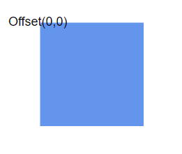 |
| (0,0.5) | 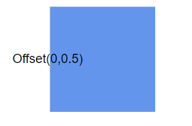 |
| (0,1) | 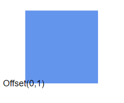 |
| (0.5,0) | 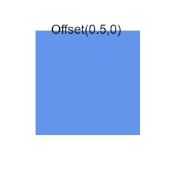 |
| (0.5,0.5) | 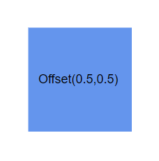 |
| (0.5,1) | 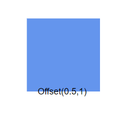 |
| (1,0) | 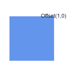 |
| (1,0.5) | 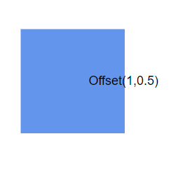 |
| (1,1) | 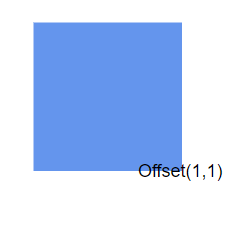 |
Note:
- Type of the offset property for node’s shape annotation is DiagramPoint.
- Type of the offset property for a connector’s path annotation is double.
- Node annotation’s Id should not start with numbers or special characters and should not contain special characters such as underscores(_) or spaces.
How to Change the Annotation Alignment
The HorizontalAlignment property of an annotation is used to set how the annotation is horizontally aligned at the annotation position determined from the fraction values. The VerticalAlignment property is used to set how the annotation is vertically aligned at the annotation position.
The following table shows all the possible alignments visually with an ‘offset of (0, 0)’.
| Horizontal Alignment | Vertical Alignment | Output with Offset(0,0) |
|---|---|---|
| Left | Top | 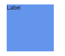 |
| Center | Top | 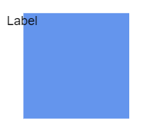 |
| Right | Top |  |
| Left | Center | 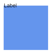 |
| Center | Center | 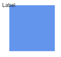 |
| Right | Center | 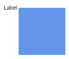 |
| Left | Bottom | 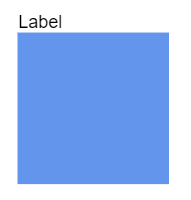 |
| Center | Bottom | 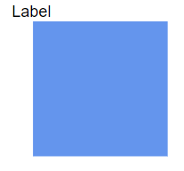 |
| Right | Bottom |  |
The following code demonstrates how to align an annotation.
@using Syncfusion.Blazor.Diagram

<SfDiagramComponent Height="600px" Nodes="@_nodes" />

@code
{
    // Defines diagram's node collection.
    DiagramObjectCollection<Node> _nodes;

    protected override void OnInitialized()
    {
        _nodes = new DiagramObjectCollection<Node>();
        Node node = new Node()
        {
            ID = "node1",
            Width = 100,
            Height = 100,
            OffsetX = 250,
            OffsetY = 250,
            Annotations = new DiagramObjectCollection<ShapeAnnotation>()
            {
                new ShapeAnnotation
                {
                    Content = "Annotation",
                    // Sets the HorizontalAlignment and VerticalAlignment for the content.
                    HorizontalAlignment = HorizontalAlignment.Center,
                    VerticalAlignment = VerticalAlignment.Center
                }
            },
            Style = new ShapeStyle() { Fill = "#6495ED", StrokeColor = "white" },
        };
        _nodes.Add(node);
    }
}A complete working sample can be downloaded from GitHub
NOTE
How to Change Annotation Margin
The Margin property adds space around the annotation. The annotations can be displaced with the margin property. The following code example explains how to align an annotation based on its Offset, HorizontalAlignment, VerticalAlignment, and Margin values.
@using Syncfusion.Blazor.Diagram

<SfDiagramComponent Height="600px" Nodes="@_nodes" />

@code
{
    // Defines diagram's node collection.
    DiagramObjectCollection<Node> _nodes;

    protected override void OnInitialized()
    {
        _nodes = new DiagramObjectCollection<Node>();
        Node node = new Node()
        {
            ID = "node1",
            Width = 100,
            Height = 100,
            OffsetX = 100,
            OffsetY = 100,
            Annotations = new DiagramObjectCollection<ShapeAnnotation>()
            {
                new ShapeAnnotation
                {
                    Content = "Task1",
                    // Sets the margin for the content.
                    Margin = new DiagramThickness() { Top = 10},
                    HorizontalAlignment = HorizontalAlignment.Center,
                    VerticalAlignment = VerticalAlignment.Top,
                    Offset = new DiagramPoint(){ X = 0.5 ,Y = 1}
                }
            },
            Style = new ShapeStyle() { Fill = "#6495ED", StrokeColor = "white" },
        };
        _nodes.Add(node);
    }
}A complete working sample can be downloaded from GitHub
How to Align the Text
The TextAlign property of an annotation’s style allows you to set how the text should be aligned (Left, Right, Center, or Justify) inside the text block. The following code explains how to set TextAlign for an annotation.
@using Syncfusion.Blazor.Diagram

<SfDiagramComponent Height="600px" Nodes="@_nodes" />

@code
{
    // Defines diagram's node collection.
    DiagramObjectCollection<Node> _nodes;

    protected override void OnInitialized()
    {
        _nodes = new DiagramObjectCollection<Node>();
        Node node = new Node()
        {
            ID = "node1",
            Width = 100,
            Height = 100,
            OffsetX = 100,
            OffsetY = 100,
            Annotations = new DiagramObjectCollection<ShapeAnnotation>()
            {
                new ShapeAnnotation
                {
                    Content = "Text align is set as Left",
                    Style = new TextStyle()
                    {
                        // Sets the textAlign as left for the content.
                        TextAlign = TextAlign.Left
                    }
                }
            },
            Style = new ShapeStyle() { Fill = "#6495ED", StrokeColor = "white" },
        };
        _nodes.Add(node);
    }
}A complete working sample can be downloaded from GitHub