Avoid overlapping with bezier
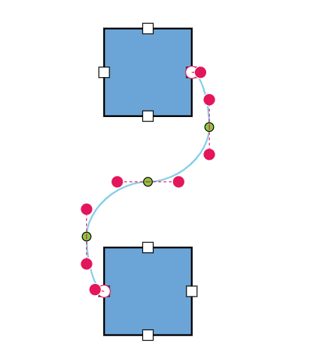
By default, when there are no segments defined for a bezier connector, the bezier segments will be created automatically and routed in such a way that avoids overlapping with the source and target nodes.
@using Syncfusion.Blazor.Diagram

<SfDiagramComponent Width="1000px" Height="500px" Nodes="@nodes" Connectors="@connectors"></SfDiagramComponent>

@code {
    //Define the diagram's connector collection.
    DiagramObjectCollection<Connector> connectors = new DiagramObjectCollection<Connector>();
    //Define the diagram's node collection.
    DiagramObjectCollection<Node> nodes = new DiagramObjectCollection<Node>();

    protected override void OnInitialized()
    {
        nodes.Add(
            new Node()
                {
                    ID = "node1",
                    OffsetX = 300,
                    OffsetY = 100,
                    Width = 100,
                    Height = 100,
                    Ports = new DiagramObjectCollection<PointPort>()
                    {
                    new PointPort()
                    {
                        ID="Port1",
                        Visibility = PortVisibility.Visible,
                        Offset = new DiagramPoint() { X = 1, Y = 0.5 },
                    },
                    }
                });
        nodes.Add(new Node()
            {
                ID = "node2",
                OffsetX = 300,
                OffsetY = 350,
                Width = 100,
                Height = 100,
                Ports = new DiagramObjectCollection<PointPort>()
                {
                    new PointPort()
                    {
                        ID="Port1",
                        Visibility = PortVisibility.Visible,
                        Offset = new DiagramPoint() { X = 0, Y = 0.5 },
                    },
                }
            });
        Connector connector1 = new Connector()
            {
                ID = "connector1",
                SourceID = "node1",
                TargetID = "node2",
                SourcePortID = "Port1",
                TargetPortID = "Port1",
                Type = ConnectorSegmentType.Bezier,
                Constraints = ConnectorConstraints.Default | ConnectorConstraints.DragSegmentThumb
            };
        connectors.Add(connector1);
    }
}
You can download a complete working sample from GitHub.
Also, if you provide segments on initial rendering, the segments collection will be updated dynamically when you move the connector ends. For static segments collection, the BezierConnectorSettings.AllowSegmentsReset property of the Connector class should be set to false.
@using Syncfusion.Blazor.Diagram

<SfDiagramComponent Width="1000px" Height="500px" Nodes="@nodes" Connectors="@connectors"></SfDiagramComponent>

@code {
    //Define the diagram's connector collection.
    DiagramObjectCollection<Connector> connectors = new DiagramObjectCollection<Connector>();
    //Define the diagram's node collection.
    DiagramObjectCollection<Node> nodes = new DiagramObjectCollection<Node>();

    protected override void OnInitialized()
    {
        nodes.Add(
            new Node()
                {
                    ID = "node1",
                    OffsetX = 300,
                    OffsetY = 100,
                    Width = 100,
                    Height = 100,
                    Ports = new DiagramObjectCollection<PointPort>()
                    {
                    new PointPort()
                    {
                        ID="Port1",
                        Visibility = PortVisibility.Visible,
                        Offset = new DiagramPoint() { X = 1, Y = 0.5 },
                    },
                    }
                });
        nodes.Add(new Node()
            {
                ID = "node2",
                OffsetX = 300,
                OffsetY = 350,
                Width = 100,
                Height = 100,
                Ports = new DiagramObjectCollection<PointPort>()
                {
                    new PointPort()
                    {
                        ID="Port1",
                        Visibility = PortVisibility.Visible,
                        Offset = new DiagramPoint() { X = 0, Y = 0.5 },
                    },
                }
            });
        Connector connector1 = new Connector()
            {
                ID = "connector1",
                SourceID = "node1",
                TargetID = "node2",
                SourcePortID = "Port1",
                TargetPortID = "Port1",
                Type = ConnectorSegmentType.Bezier,
                Segments = new DiagramObjectCollection<ConnectorSegment>(){new BezierSegment(){Type = ConnectorSegmentType.Bezier}},
                //Define whether to reset the current segments collection in response to change in the connector ends.
                BezierConnectorSettings = new BezierConnectorSettings() { AllowSegmentsReset = false },
                Constraints = ConnectorConstraints.Default | ConnectorConstraints.DragSegmentThumb
            };
        connectors.Add(connector1);
    }
}
You can download a complete working sample from GitHub.
How to interact with the bezier segments efficiently
While interacting with multiple bezier segments, maintain their control points at the same distance and angle by using the BezierConnectorSettings.Smoothness property of the Connector class.
| BezierSmoothness value | Description | Output |
|---|---|---|
| SymmetricDistance | Both control points of adjacent segments will be at the same distance when one of them is editing. |  |
| SymmetricAngle | Both control points of adjacent segments will be at the same angle when one of them is editing. |  |
| Both | Both control points of adjacent segments will be at the same angle and same distance when one of them is editing. |  |
| None | Segment’s control points interact independently from each other. |  |
Also, the intermediate point of two adjacent bezier segments can be edited interactively based on the BezierConnectorSettings.SegmentEditOrientation property of the Connector class.
| SegmentEditOrientation value | Description | Output |
|---|---|---|
| Bidirectional | It allows the intermediate points to be dragged in either vertical or horizontal directions. |  |
| Freeform | It allows the intermediate points to be dragged in any direction. |  |
The following code illustrates how to interact with bezier efficiently by using BezierConnectorSettings.Smoothness and BezierConnectorSettings.SegmentEditOrientation property of the Connector class.
@using Syncfusion.Blazor.Diagram

<SfDiagramComponent Width="1000px" Height="500px" Nodes="@nodes" Connectors="@connectors"></SfDiagramComponent>

@code {
    //Define the diagram's connector collection.
    DiagramObjectCollection<Connector> connectors = new DiagramObjectCollection<Connector>();
    //Define the diagram's node collection.
    DiagramObjectCollection<Node> nodes = new DiagramObjectCollection<Node>();

    protected override void OnInitialized()
    {
        nodes.Add(
            new Node()
                {
                    ID = "node1",
                    OffsetX = 300,
                    OffsetY = 100,
                    Width = 100,
                    Height = 100,
                    Ports = new DiagramObjectCollection<PointPort>()
                    {
                    new PointPort()
                    {
                        ID="Port1",
                        Visibility = PortVisibility.Visible,
                        Offset = new DiagramPoint() { X = 1, Y = 0.5 },
                    },
                    }
                });
        nodes.Add(new Node()
            {
                ID = "node2",
                OffsetX = 300,
                OffsetY = 350,
                Width = 100,
                Height = 100,
                Ports = new DiagramObjectCollection<PointPort>()
                {
                    new PointPort()
                    {
                        ID="Port1",
                        Visibility = PortVisibility.Visible,
                        Offset = new DiagramPoint() { X = 0, Y = 0.5 },
                    },
                }
            });
        Connector connector1 = new Connector()
            {
                ID = "connector1",
                SourceID = "node1",
                TargetID = "node2",
                SourcePortID = "Port1",
                TargetPortID = "Port1",
                Type = ConnectorSegmentType.Bezier,
                BezierConnectorSettings = new BezierConnectorSettings()
                {
                    //Define the smoothness for a bezier connector.
                    Smoothness = BezierSmoothness.SymmetricAngle,
                    //Define the orientation of the segment editing controls.
                    SegmentEditOrientation = BezierSegmentEditOrientation.Freeform
                },
                Constraints = ConnectorConstraints.Default | ConnectorConstraints.DragSegmentThumb
            };
        connectors.Add(connector1);
    }
}
You can download a complete working sample from GitHub.
How to show or hide the bezier segment’s control points
By using the BezierConnectorSettings.ControlPointsVisibility property of the Connector class, you can enable or disable the visibility of the bezier segment’s control points.
| ControlPointsVisibility value | Description | Output |
|---|---|---|
| None | It allows you to hide all control points of the bezier connector. | 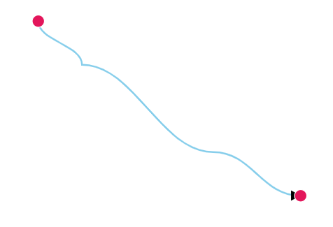 |
| Source | It allows you to show control points of the source segment and hides all other control points in a bezier connector. | 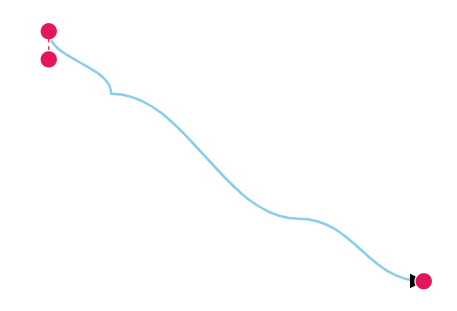 |
| Target | It allows you to show control points of the target segment and hides all other control points in a bezier connector. | 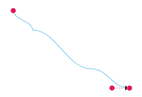 |
| Intermediate | It allows you to show control points of the intermediate segments and hides all other control points in a bezier connector. | 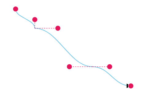 |
| All | It allows you to show all the control points of the bezier connector, including the source, target, and intermediate segments’ control points. | 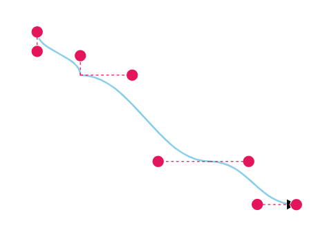 |
@using Syncfusion.Blazor.Diagram
<SfDiagramComponent Width="1000px" Height="500px" Connectors="@connectors"></SfDiagramComponent>
@code {
    //Define the diagram's connector collection.
    DiagramObjectCollection<Connector> connectors = new DiagramObjectCollection<Connector>();
    protected override void OnInitialized()
    {
        Connector connector1 = new Connector()
        {
            ID = "connector1",
            SourcePoint = new DiagramPoint() { X = 700, Y = 200 },
            TargetPoint = new DiagramPoint() { X = 1000, Y = 400 },
            Segments = new DiagramObjectCollection<ConnectorSegment>()
            {
                new BezierSegment(){Type = ConnectorSegmentType.Bezier, Point = new DiagramPoint(){X = 750, Y = 250}},
                new BezierSegment(){Type = ConnectorSegmentType.Bezier, Point = new DiagramPoint(){X = 900, Y = 350}}
            },
            Type = ConnectorSegmentType.Bezier,
            BezierConnectorSettings = new BezierConnectorSettings()
            {
                //Define the visibility of the control points.
                ControlPointsVisibility = ControlPointsVisibility.Intermediate
            },
        };
        connectors.Add(connector1);
    }
}
You can download a complete working sample from GitHub.