How can I help you?
Flowchart Layout in Blazor Diagram Component
10 Jun 202624 minutes to read
The Flowchart layout provides a visual representation of processes, workflows, systems, or algorithms. It uses standard symbols to depict different actions, with arrows connecting these symbols to indicate the flow or direction of the process. Flowcharts help communicate step-by-step sequences, making complex processes easier to understand and communicate.
How to Use Common Flowchart Symbols
Different flowchart symbols have different meanings that are used to represent various states in flowchart. The following table describes the most common flowchart symbols that are used in creating flowchart.
| Symbol | Shape name | Description |
|---|---|---|
 |
Terminator | Indicates the beginning and ending of the process. |
 |
Data | Indicates data input or output for a process. |
 |
Process | Represents an operation or set of operations and data manipulations. |
 |
Decision | Shows a branching point where the decision is made to choose one of the two paths |
 |
Document | Represents a single document or report in the process. |
 |
PreDefinedProcess | Represents a sequence of actions that combine to perform a specific task that is defined elsewhere. |
 |
DirectData | Represents a collection of information that allows searching, sorting, and filtering. |
 |
StoredData | Represents a step where data get stored within a process. |
 |
ManualInput | Represents the manual input of data into a field or step in a process. |
 |
ManualOperation | Represents an operation in a process that must be done manually, not automatically. |
 |
Preparation | Represents a setup or initialization process to another step in the process. |
 |
OffPageReference | Represents a labeled connector used to link two flowcharts on different pages. |
 |
MultiDocument | Represents multiple documents or reports in the process. |
 |
Represents a direction of flow from one step to another. It will get created automatically based on the relationship between the parent and child. |
@using Syncfusion.Blazor.Diagram

<SfDiagramComponent @ref="Diagram" Width="100%" Height="900px" ConnectorCreating="@OnConnectorCreating" NodeCreating="@OnNodeCreating" DataLoaded="@OnDataLoaded">
    <DataSourceSettings ID="Id" ParentID="ParentId" DataSource="DataSource"> </DataSourceSettings>
    <Layout Type="LayoutType.Flowchart" HorizontalSpacing="50" Orientation="LayoutOrientation.TopToBottom" VerticalSpacing="50" FlowchartLayoutSettings="@flowchartSettings">
    </Layout>
</SfDiagramComponent>

@code
{
    //Initialize diagram component.
    private SfDiagramComponent _diagram;
    //Initialize flowchart layout settings.
    private FlowchartLayoutSettings _flowchartSettings = new FlowchartLayoutSettings()
    {
        YesBranchDirection = BranchDirection.LeftInFlow,
        NoBranchDirection = BranchDirection.RightInFlow
    };

    private void OnDataLoaded(object obj)
    {
        for (int i = 0; i < _diagram.Connectors.Count; i++)
        {
            Connector connector = _diagram.Connectors[i];
            Node node = _diagram.GetObject(connector.TargetID) as Node;
            Node srcNode = _diagram.GetObject(connector.SourceID) as Node;
            if (node.Data != null && node.Data is ItemInfo itemInfo)
            {
                if (itemInfo.Label != null && itemInfo.Label.Count > 0)
                {
                    if (itemInfo.ParentId.IndexOf((srcNode.Data as ItemInfo).Id) != -1)
                    {
                        var parentIndex = itemInfo.ParentId.IndexOf((srcNode.Data as ItemInfo).Id);
                        if (itemInfo.Label.Count > parentIndex)
                        {
                            connector.Annotations = new DiagramObjectCollection<PathAnnotation>()
                            {
                                new PathAnnotation() { Content = itemInfo.Label[parentIndex], Style = new TextStyle(){ Bold = true} }
                            };
                        }
                    }
                }
            }
        }
    }

    //Creates connectors with some default values.
    private void OnConnectorCreating(IDiagramObject obj)
    {
        if (obj is Connector connector)
        {
            connector.Type = ConnectorSegmentType.Orthogonal;
        }
    }

    //Creates nodes with some default values.
    private void OnNodeCreating(IDiagramObject obj)
    {
        Node node = obj as Node;
        if (node.Data != null && node.Data is ItemInfo)
        {
            ItemInfo employeeDetails = node.Data as ItemInfo;
            node.Width = employeeDetails._Width;
            node.Height = employeeDetails._Height;
            if (employeeDetails._Shape == "StartOrEnd")
            {
                node.Shape = new FlowShape() { Shape = NodeFlowShapes.Terminator };
            }
            else
                node.Shape = new FlowShape() { Shape = (NodeFlowShapes)Enum.Parse(typeof(NodeFlowShapes), employeeDetails._Shape.ToString()) };
            node.Style.Fill = employeeDetails._Color;
            node.Style.StrokeColor = employeeDetails._Color;
            node.Annotations = new DiagramObjectCollection<ShapeAnnotation>()
            {
                new ShapeAnnotation(){ Content = employeeDetails.Name, Style = new TextStyle(){ Color = "white", Bold = true} }
            };
        }
    }

    //Initialize data source collection.
    public List<ItemInfo> DataSource = new List<ItemInfo>(){
        new ItemInfo()
        {
            Id = "1",
            Name = "Start",
            _Shape = "StartOrEnd",
            _Width = 80,
            _Height = 35,
            _Color = "#6CA0DC"
        },
        new ItemInfo()
        {
            Id = "2",
            Name = "Input",
            ParentId = new List<string> { "1" },
            _Shape = "Data",
            _Width = 90,
            _Height = 35,
            _Color = "#6CA0DC"
        },
        new ItemInfo()
        {
            Id = "3",
            Name = "Decision?",
            ParentId = new List<string> { "2" },
            _Shape = "Decision",
            _Width = 80,
            _Height = 60,
            _Color = "#6CA0DC"
        },
        new ItemInfo()
        {
            Id = "4",
            Label = new List<string> { "No" },
            Name = "Process1",
            ParentId = new List<string> { "3" },
            _Shape = "Process",
            _Width = 80,
            _Height = 40,
            _Color = "#6CA0DC"
        },
        new ItemInfo()
        {
            Id = "5",
            Label = new List<string> { "Yes" },
            Name = "Process2",
            ParentId = new List<string>() { "3" },
            _Shape = "Process",
            _Width = 80,
            _Height = 40,
            _Color = "#6CA0DC"
        },
        new ItemInfo()
        {
            Id = "6",
            Name = "Output",
            ParentId = new List<string> { "5" },
            _Shape = "Data",
            _Width = 90,
            _Height = 35,
            _Color = "#6CA0DC"
        },
        new ItemInfo()
        {
            Id = "7",
            Name = "Output",
            ParentId = new List<string> { "4" },
            _Shape = "Data",
            _Width = 90,
            _Height = 35,
            _Color = "#6CA0DC"
        },
        new ItemInfo()
        {
            Id = "8",
            Name = "End",
            ParentId = new List<string> { "6", "7" },
            _Shape = "Terminator",
            _Width = 80,
            _Height = 35,
            _Color = "#6CA0DC"
        },
    };

    public class ItemInfo
    {
        public string Name { get; set; }
        public string Id { get; set; }
        public List<string> Label { get; set; }
        public List<string> ParentId { get; set; }
        public string _Shape { get; set; }
        public double _Width { get; set; }
        public double _Height { get; set; }
        public string _Color { get; set; }
    }
}
Note: When rendering a flowchart layout using a data source, connector labels must be applied manually in the DataLoaded event.
A complete working sample can be downloaded from GitHub.
How to Customize Flowchart Layout Orientation
The sequence of a node’s direction can be customized by flowchart’s orientation, either vertically from top to bottom or horizontally from left to right. The Orientation property of the layout class allows you to define the flow direction for the flowchart as either TopToBottom or LeftToRight.
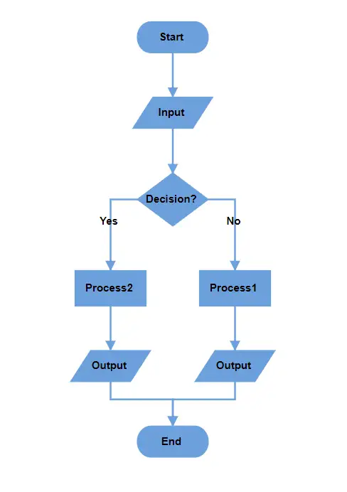
How to Arrange Layout Using TopToBottom Orientation
This orientation arranges elements vertically from top to bottom. It is commonly used to represent sequential progression in a process.
@using Syncfusion.Blazor.Diagram

<SfDiagramComponent @ref="_diagram" Height="500px">
    <Layout Type="LayoutType.Flowchart" Orientation="LayoutOrientation.TopToBottom">
    </Layout>
</SfDiagramComponent>

@code
{
    private SfDiagramComponent _diagram;
}
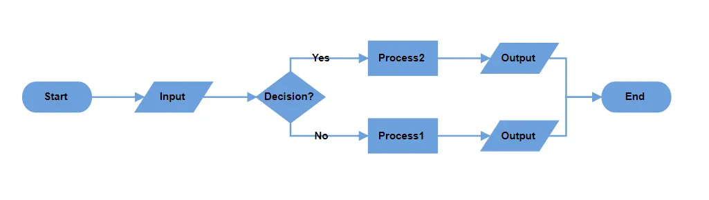
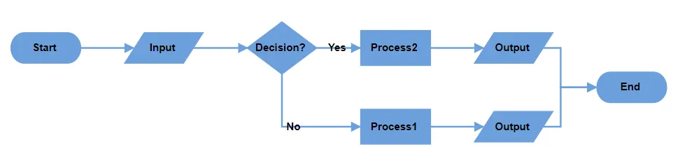
How to Arrange Layout Using LeftToRight Orientation
This Orientation arranges elements horizontally from left to right. It is used to represent processes or workflows that move sequentially across the page, emphasizing a linear progression of steps or actions.
@using Syncfusion.Blazor.Diagram

<SfDiagramComponent @ref="_diagram" Height="500px">
    <Layout Type="LayoutType.Flowchart" Orientation="LayoutOrientation.LeftToRight">
    </Layout>
</SfDiagramComponent>

@code
{
    private SfDiagramComponent _diagram;
}
How to Customize Decision Output Directions
The decision symbol represents a question or condition that leads to different paths based on a binary outcome (Yes/No, True/False). Customize the output direction of these paths using the YesBranchDirection and NoBranchDirection properties of the FlowchartLayoutSettings.
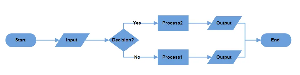
Left In Flow - Places the branch to the left of the decision symbol.
Right In Flow - Places the branch to the right of the decision symbol.
Same As Flow - Aligns the branch in the same direction as the flow of the decision symbol.
The following table will explain the pictorial representation of the behavior:
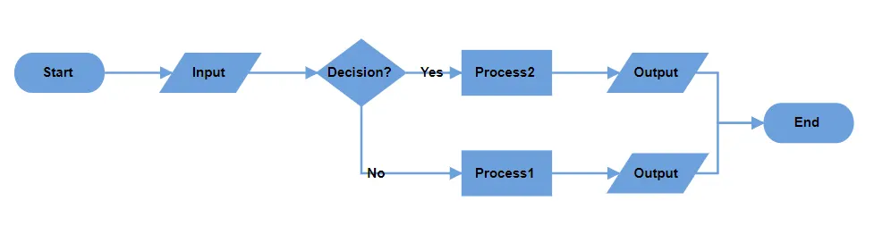
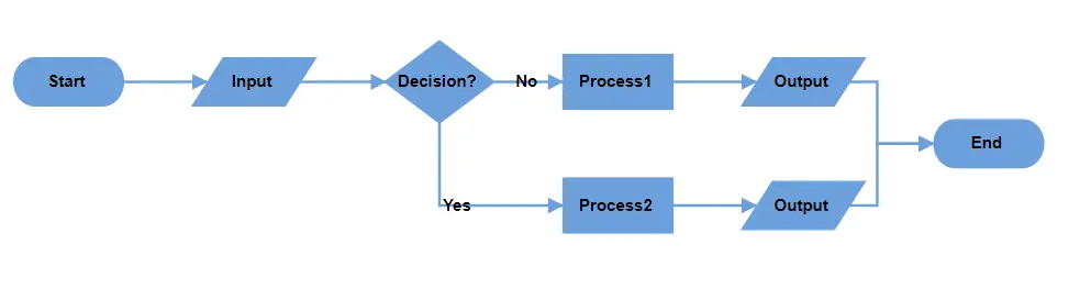
| YesBranchDirection | NoBranchDirection | TopToBottom | LeftToRight |
|---|---|---|---|
| Left In Flow | Right In Flow | 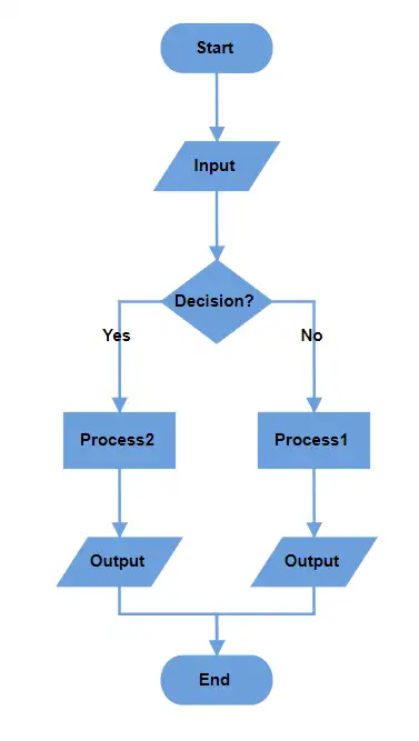 |
 |
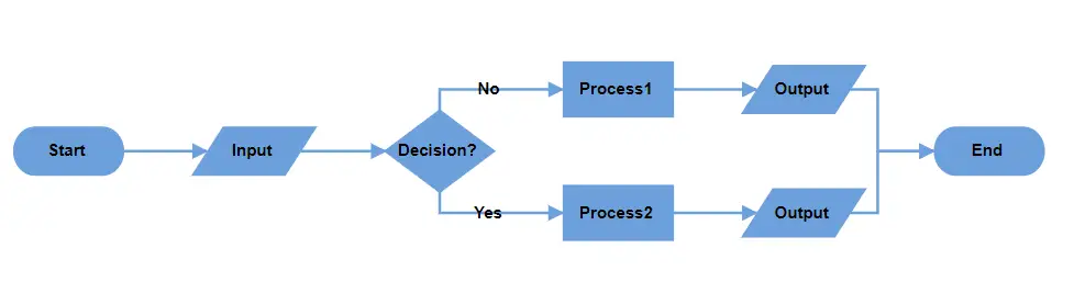
| Right In Flow | Left In Flow | 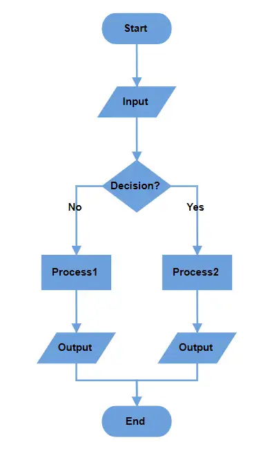 |
 |
| Same As Flow | Right In Flow | 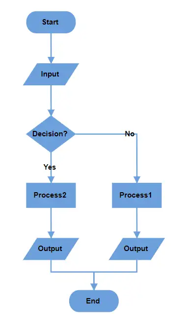 |
 |
| Right In Flow | Same As Flow | 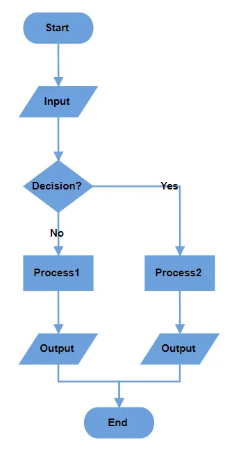 |
 |
| Same As Flow | Same As Flow | 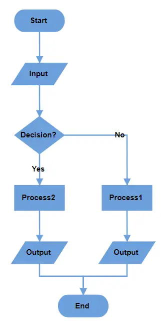 |
 |
Note: If both branch directions are the same, the Yes branch is prioritized.
A complete working sample can be downloaded from GitHub.
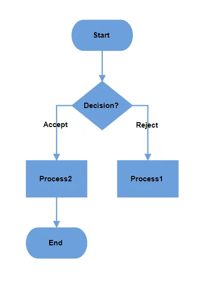
How to Define Custom Yes and No Branch Values
The decision symbol produces two branches: Yes and No. If the output branch connector text value matches the values in the YesBranchValues property of FlowchartLayoutSettings, it is considered the Yes branch. Similarly, if the connector text value matches the values in the NoBranchValues property, it will be considered as the No branch. By default, YesBranchValues property contains Yes and True string values and the NoBranchValues property contains No and False string values.
Any text value can be given as a connector text to describe the flow. Also, any string value can be given in the YesBranchValues and NoBranchValues. To decide the flow based on if or else, the connector text should match the values in the YesBranchValues and NoBranchValues.
@using Syncfusion.Blazor.Diagram

<SfDiagramComponent @ref="Diagram" Width="100%" Height="900px" ConnectorCreating="@OnConnectorCreating" NodeCreating="@OnNodeCreating" DataLoaded="@OnDataLoaded">
    <DataSourceSettings ID="Id" ParentID="ParentId" DataSource="DataSource"> </DataSourceSettings>
    <Layout Type="LayoutType.Flowchart" HorizontalSpacing="50" Orientation="LayoutOrientation.TopToBottom" VerticalSpacing="50" FlowchartLayoutSettings="@flowchartSettings">
    </Layout>
</SfDiagramComponent>

@code
{
    //Initialize diagram component.
    private SfDiagramComponent _diagram;
    //Initialize flowchart layout settings.
    private FlowchartLayoutSettings _flowchartSettings = new FlowchartLayoutSettings()
    {
        YesBranchValues = new List<string> { "Accept", "Yes" },
        NoBranchValues = new List<string> { "Reject", "No" },
    };

    private void OnDataLoaded(object obj)
    {
        for (int i = 0; i < _diagram.Connectors.Count; i++)
        {
            Connector connector = _diagram.Connectors[i];
            Node node = _diagram.GetObject(connector.TargetID) as Node;
            Node srcNode = _diagram.GetObject(connector.SourceID) as Node;
            if (node.Data != null && node.Data is ItemInfo itemInfo)
            {
                if (itemInfo.Label != null && itemInfo.Label.Count > 0)
                {
                    if (itemInfo.ParentId.IndexOf((srcNode.Data as ItemInfo).Id) != -1)
                    {
                        var parentIndex = itemInfo.ParentId.IndexOf((srcNode.Data as ItemInfo).Id);
                        if (itemInfo.Label.Count > parentIndex)
                        {
                            connector.Annotations = new DiagramObjectCollection<PathAnnotation>()
                            {
                                new PathAnnotation() { Content = itemInfo.Label[parentIndex], Style = new TextStyle(){ Bold = true} }
                            };
                        }
                    }
                }
            }
        }
    }

    //Creates connectors with some default values.
    private void OnConnectorCreating(IDiagramObject obj)
    {
        if (obj is Connector connector)
        {
            connector.Type = ConnectorSegmentType.Orthogonal;
        }
    }

    //Creates nodes with some default values.
    private void OnNodeCreating(IDiagramObject obj)
    {
        Node node = obj as Node;
        if (node.Data != null && node.Data is ItemInfo)
        {
            ItemInfo employeeDetails = node.Data as ItemInfo;
            node.Width = employeeDetails._Width;
            node.Height = employeeDetails._Height;
            if (employeeDetails._Shape == "StartOrEnd")
            {
                node.Shape = new FlowShape() { Shape = NodeFlowShapes.Terminator };
            }
            else
                node.Shape = new FlowShape() { Shape = (NodeFlowShapes)Enum.Parse(typeof(NodeFlowShapes), employeeDetails._Shape.ToString()) };
            node.Style.Fill = employeeDetails._Color;
            node.Style.StrokeColor = employeeDetails._Color;
            node.Annotations = new DiagramObjectCollection<ShapeAnnotation>()
            {
                new ShapeAnnotation(){ Content = employeeDetails.Name, Style = new TextStyle(){ Color = "white", Bold = true} }
            };
        }
    }

    //Initialize data source collection.
    public List<ItemInfo> DataSource = new List<ItemInfo>(){
        new ItemInfo()
        {
            Id = "1",
            Name = "Start",
            _Shape = "StartOrEnd",
            _Width = 100,
            _Height = 50,
            _Color = "#6CA0DC"
        },
        new ItemInfo()
        {
            Id = "2",
            Name = "Decision?",
            ParentId = new List<string> { "1" },
            _Shape = "Decision",
            _Width = 100,
            _Height = 80,
            _Color = "#6CA0DC"
        },
        new ItemInfo()
        {
            Id = "3",
            Label = new List<string> { "Reject" },
            Name = "Process1",
            ParentId = new List<string> { "2" },
            _Shape = "Process",
            _Width = 100,
            _Height = 60,
            _Color = "#6CA0DC"
        },
        new ItemInfo()
        {
            Id = "4",
            Label = new List<string> { "Accept" },
            Name = "Process2",
            ParentId = new List<string>() { "2" },
            _Shape = "Process",
            _Width = 100,
            _Height = 60,
            _Color = "#6CA0DC"
        },
        new ItemInfo()
        {
            Id = "5",
            Name = "End",
            ParentId = new List<string> { "4" },
            _Shape = "Terminator",
            _Width = 100,
            _Height = 50,
            _Color = "#6CA0DC"
        },
    };

    public class ItemInfo
    {
        public string Name { get; set; }
        public string Id { get; set; }
        public List<string> Label { get; set; }
        public List<string> ParentId { get; set; }
        public string _Shape { get; set; }
        public double _Width { get; set; }
        public double _Height { get; set; }
        public string _Color { get; set; }
    }
}
A complete working sample can be downloaded from GitHub.
How to Update Spacing Between Nodes
Control the spacing between node using the HorizontalSpacing and VerticalSpacing in the layout. These properties adjust the distance between nodes horizontally and vertically, giving you precise control over the appearance and organization of your diagram.