NOTE
Syncfusion® recommends using Blazor Diagram Component which provides better performance than this diagram control. Blazor Diagram Component will be actively developed in the future.
Segments in Blazor Diagram Component
29 Nov 202419 minutes to read
The path of the connector is defined with a collection of segments. There are three types of segments.
Straight
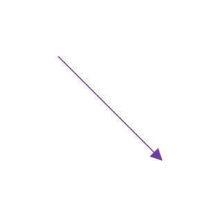
To create a straight line, specify the Type of the segment as straight and add a straight segment to Segments collection and need to specify Type for the connector. The following code example illustrates how to create a default straight segment.
@using Syncfusion.Blazor.Diagrams
@using System.Collections.ObjectModel

<SfDiagram Height="600px" Connectors="@ConnectorCollection">
</SfDiagram>

@code
{
    //Defines diagram's connector collection
    public ObservableCollection<DiagramConnector> ConnectorCollection = new ObservableCollection<DiagramConnector>();
    //Defines the diagram constraints.
    public DiagramConstraints diagramConstraints = DiagramConstraints.Default;

    protected override void OnInitialized()
    {
        DiagramConnector diagramConnector = new DiagramConnector()
        {
            SourcePoint = new ConnectorSourcePoint() { X = 100, Y = 100 },
            TargetPoint = new ConnectorTargetPoint() { X = 200, Y = 200 },
            TargetDecorator = new ConnectorTargetDecorator()
            {
                Shape = DecoratorShapes.Arrow,
                Style = new DecoratorShapeStyle()
                {
                    Fill = "#6f409f",
                    StrokeColor = "#6f409f",
                    StrokeWidth = 1
                }
            },
            Style = new ConnectorShapeStyle()
            {
                StrokeColor = "#6f409f",
                StrokeWidth = 1
            },

            //Specify the segment type as straight.
            Type = Segments.Straight,
        };
        ConnectorCollection.Add(diagramConnector);
    }
}
Orthogonal
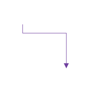
Orthogonal segments are used to create segments that are perpendicular to each other. Set the segment Type as orthogonal to create a default orthogonal segment and need to specify Type. The following code example illustrates how to create a default orthogonal segment.
Multiple segments can be defined one after another. To create a connector with multiple segments, define and add the segments to connector.Segments collection. The following code example illustrates how to create a connector with multiple segments.
@using Syncfusion.Blazor.Diagrams
@using System.Collections.ObjectModel

<SfDiagram Height="600px" Connectors="@ConnectorCollection">
</SfDiagram>

@code
{
    //Defines diagram's connector collection
    public ObservableCollection<DiagramConnector> ConnectorCollection = new ObservableCollection<DiagramConnector>();
    public DiagramConstraints diagramConstraints = DiagramConstraints.Default;

    protected override void OnInitialized()
    {
        DiagramConnector diagramConnector = new DiagramConnector()
        {
            SourcePoint = new ConnectorSourcePoint() { X = 100, Y = 100 },
            TargetPoint = new ConnectorTargetPoint() { X = 200, Y = 200 },
            TargetDecorator = new ConnectorTargetDecorator()
            {
                Shape = DecoratorShapes.Arrow,
                Style = new DecoratorShapeStyle()
                {
                    Fill = "#6f409f",
                    StrokeColor = "#6f409f",
                    StrokeWidth = 1
                }
            },
            Style = new ConnectorShapeStyle()
            {
                StrokeColor = "#6f409f",
                StrokeWidth = 1
            },

            //Specify the segments type as Orthogonal.
            Type = Segments.Orthogonal,
        };
        ConnectorCollection.Add(diagramConnector);
    }
}
The Length and Direction properties allow to define the flow and length of segment. The following code example illustrates how to create customized orthogonal segments.
@using Syncfusion.Blazor.Diagrams
@using System.Collections.ObjectModel

<SfDiagram Height="600px" Connectors="@ConnectorCollection">
</SfDiagram>

@code
{
    //Defines diagram's connector collection
    public ObservableCollection<DiagramConnector> ConnectorCollection = new ObservableCollection<DiagramConnector>();

    public DiagramConstraints diagramConstraints = DiagramConstraints.Default;

    protected override void OnInitialized()
    {
        DiagramConnector diagramConnector = new DiagramConnector()
        {
            SourcePoint = new ConnectorSourcePoint() { X = 100, Y = 100 },
            TargetPoint = new ConnectorTargetPoint() { X = 200, Y = 200 },
            TargetDecorator = new ConnectorTargetDecorator()
            {
                Shape = DecoratorShapes.Arrow,
                Style = new DecoratorShapeStyle()
                {
                    Fill = "#6f409f",
                    StrokeColor = "#6f409f",
                    StrokeWidth = 1
                }
            },
            Style = new ConnectorShapeStyle()
            {
                StrokeColor = "#6f409f",
                StrokeWidth = 1
            },
            //Specify the connector type as orthogonal.
            Type = Segments.Orthogonal,
            //Initialize the segments collection
            Segments = new ObservableCollection<DiagramConnectorSegment>()
            {
                //Create a new segment with length and direction
                new DiagramConnectorSegment()
                {
                    Length = 100,
                    Type = Segments.Orthogonal,
                    Direction = Direction.Right,
                },
                //Create another new segment with length and direction
                new DiagramConnectorSegment()
                {
                    Length = 100,
                    Type = Segments.Orthogonal,
                    Direction = Direction.Bottom,
                }
            },
        };
        ConnectorCollection.Add(diagramConnector);
    }
}
NOTE
You need to mention the segment type as same as what you mentioned in connector type. There should be no contradiction between connector type and segment type.
Avoid overlapping
Orthogonal segments are automatically re-routed, in order to avoid overlapping with the source and target nodes. The following preview illustrates how orthogonal segments are re-routed.
@using Syncfusion.Blazor.Diagrams
@using System.Collections.ObjectModel

<SfDiagram Height="600px" Nodes="@NodeCollection" Connectors="@ConnectorCollection">
</SfDiagram>
@code
{
    public ObservableCollection<DiagramNode> NodeCollection = new ObservableCollection<DiagramNode>();

    public ObservableCollection<DiagramConnector> ConnectorCollection = new ObservableCollection<DiagramConnector>();

    public DiagramConstraints diagramConstraints = DiagramConstraints.Default;

    protected override void OnInitialized()
    {
        //Create source node
        DiagramNode node1 = new DiagramNode()
        {
            OffsetX = 100,
            OffsetY = 100,
            Height = 50,
            Width = 100,
            Id = "node1",
            Shape = new DiagramShape()
            {
                Type = Syncfusion.Blazor.Diagrams.Shapes.Basic,
                BasicShape = BasicShapes.Ellipse
            },
            Style = new NodeShapeStyle()
            {
                Fill = "#37909A",
                StrokeColor = "#37909A",
            },
            Ports = new ObservableCollection<DiagramPort>()
            {
                new DiagramPort()
                {
                    Id = "port1",
                    Offset = new Syncfusion.Blazor.Diagrams.NodePortOffset() { X = 1, Y = 0.5 },
                    Height = 10,
                    Width = 10,
                    Visibility = PortVisibility.Visible,
                    Style = new PortShapeStyle()
                    {
                        Fill = "yellow",
                        StrokeColor = "yellow"
                    }
                },
            },
        };
        //Add node into node's collection
        NodeCollection.Add(node1);

        //Create target node
        DiagramNode node2 = new DiagramNode()
        {
            OffsetX = 300,
            OffsetY = 300,
            Height = 50,
            Width = 100,
            Id = "node2",
            Shape = new DiagramShape()
            {
                Type = Syncfusion.Blazor.Diagrams.Shapes.Basic,
                BasicShape = BasicShapes.Ellipse
            },
            Style = new NodeShapeStyle()
            {
                Fill = "#37909A",
                StrokeColor = "#37909A",
            },
            Ports = new ObservableCollection<DiagramPort>()
            {
                new DiagramPort()
                {
                    Id = "port2",
                    Offset = new Syncfusion.Blazor.Diagrams.NodePortOffset() { X = 0, Y = 0.5 },
                    Height = 10,
                    Width = 10,
                    Visibility = PortVisibility.Visible,
                    Style = new PortShapeStyle()
                    {
                        Fill = "yellow",
                        StrokeColor = "yellow"
                    }
                },
            },
        };
        //Add node into node's collection
        NodeCollection.Add(node2);
        //Create a connector.
        DiagramConnector diagramConnector = new DiagramConnector()
        {
            SourceID = "node1",
            TargetID = "node2",
            SourcePortID = "port1",
            TargetPortID = "port2",
            TargetDecorator = new ConnectorTargetDecorator()
            {
                Shape = DecoratorShapes.Arrow,
                Style = new DecoratorShapeStyle()
                {
                    Fill = "#37909A",
                    StrokeColor = "#37909A",
                    StrokeWidth = 1
                }
            },
            Style = new ConnectorShapeStyle()
            {
                StrokeColor = "#37909A",
                StrokeWidth = 1
            },
            Type = Segments.Orthogonal,
        };
        ConnectorCollection.Add(diagramConnector);
    }
}
Bezier
Bezier segments are used to create curve segments and the curves are configurable either with the control points or with vectors.
To create a bezier segment, the Type of the segment is set as bezier and need to specify type for the connector. The following code example illustrates how to create a default bezier segment.
@using Syncfusion.Blazor.Diagrams
@using System.Collections.ObjectModel

<SfDiagram Height="600px" Connectors="@ConnectorCollection">
</SfDiagram>

@code
{
    //Defines diagram's connector collection
    public ObservableCollection<DiagramConnector> ConnectorCollection = new ObservableCollection<DiagramConnector>();

    protected override void OnInitialized()
    {
        DiagramConnector diagramConnector = new DiagramConnector()
        {
            SourcePoint = new ConnectorSourcePoint() { X = 100, Y = 100 },
            TargetPoint = new ConnectorTargetPoint() { X = 200, Y = 200 },
            TargetDecorator = new ConnectorTargetDecorator()
            {
                Shape = DecoratorShapes.Arrow,
                Style = new DecoratorShapeStyle()
                {
                    Fill = "#6f409f",
                    StrokeColor = "#6f409f",
                    StrokeWidth = 1
                }
            },
            Style = new ConnectorShapeStyle()
            {
                StrokeColor = "#6f409f",
                StrokeWidth = 1
            },
            Type = Segments.Bezier,
        };
        //Add the connector into connectors's collection.
        ConnectorCollection.Add(diagramConnector);
    }
}