Interaction in Diagram Component
3 Jul 202624 minutes to read
Connectors support interactive operations such as selection, dragging, and routing to improve diagram editing and readability.
How to Select and Deselect Connectors
At runtime, a connector can be selected by using the Select method and the current selection can be cleared by using ClearSelection. The following example demonstrates how to select and clear selection in the diagram.
@using Syncfusion.Blazor.Diagram
@using System.Collections.ObjectModel
@using Syncfusion.Blazor.Buttons

<SfButton Content="Select" OnClick="@OnSelect" />
<SfButton Content="UnSelect" OnClick="@UnSelect" />
<SfDiagramComponent @ref="_diagram" Width="1000px" Height="500px" Connectors="@_connectors">
</SfDiagramComponent>

@code
{
    private SfDiagramComponent _diagram;
    private DiagramObjectCollection<Connector> _connectors = new DiagramObjectCollection<Connector>();

    protected override void OnInitialized()
    {
        var connectorInfo = new Dictionary<string, object>();
        connectorInfo.Add("connectorInfo", "Central Connector");
        var connector = new Connector()
        {
            ID = "connector1",
            SourcePoint = new DiagramPoint()
            {
                X = 100,
                Y = 100
            },
            TargetPoint = new DiagramPoint()
            {
                X = 200,
                Y = 200
            },
            Type = ConnectorSegmentType.Orthogonal,
            TargetDecorator = new DecoratorSettings()
            {
                Shape = DecoratorShape.Arrow,
                Style = new ShapeStyle()
                {
                    Fill = "#6495ED",
                    StrokeColor = "#6495ED",
                    StrokeWidth = 1
                }
            },
            Style = new ShapeStyle()
            {
                StrokeColor = "#6495ED",
                StrokeWidth = 1
            },
            AdditionalInfo = connectorInfo
        };
        _connectors.Add(connector);
    }

    private void OnSelect()
    {
        // Select the Connector.
        _diagram.Select(new ObservableCollection<IDiagramObject> { _diagram.GetObject(_diagram.Connectors[0].ID) as IDiagramObject });
    }

    private void UnSelect()
    {
        // Clear selection in the diagram.
        _diagram.ClearSelection();
    }
}A complete working sample can be downloaded from GitHub
Selection can also be performed through user interaction:
- Click an element to select it.
- When elements are selected in the diagram, the SelectionChanging and SelectionChanged events are triggered, allowing customization during the selection process.
How to Drag a Connector
A connector can be programmatically moved at runtime by using the Drag method. The following example shows how to drag the connector by using the drag method.
@using Syncfusion.Blazor.Diagram
@using Syncfusion.Blazor.Buttons

<SfButton Content="Drag" OnClick="@OnDrag" />
<SfDiagramComponent @ref="_diagram" Width="1000px" Height="500px" Connectors="@_connectors" />

@code
{
    //Reference the diagram
    private SfDiagramComponent _diagram;
    //Intialize the connector collection
    private DiagramObjectCollection<Connector> _connectors = new DiagramObjectCollection<Connector>();

    protected override void OnInitialized()
    {
        Dictionary<string, object> ConnectorInfo = new Dictionary<string, object>();
        ConnectorInfo.Add("connectorInfo", "Central Connector");
        Connector Connector = new Connector()
        {
            ID = "connector1",
            SourcePoint = new DiagramPoint()
            {
                X = 100,
                Y = 100
            },
            TargetPoint = new DiagramPoint()
            {
                X = 200,
                Y = 200
            },
            Type = ConnectorSegmentType.Orthogonal,
            TargetDecorator = new DecoratorSettings()
            {
                Shape = DecoratorShape.Arrow,
                Style = new ShapeStyle()
                {
                    Fill = "black",
                    StrokeColor = "black",
                    StrokeWidth = 1
                }
            },
            Style = new ShapeStyle()
            {
                StrokeColor = "black",
                StrokeWidth = 1
            },
            AdditionalInfo = ConnectorInfo
        };
        _connectors.Add(Connector);
    }

    private void OnDrag()
    {
        // Drag the connector
        _diagram.Drag(_diagram.Connectors[0], 10, 10);
    }
}
A complete working sample can be downloaded from GitHub
Connectors can also be dragged through user interaction:
- Drag an object by clicking and dragging it. When multiple elements are selected, dragging any one of the selected elements move all the selected elements.
- While dragging, the PositionChanging and PositionChanged events are triggered and allow customization in these events.
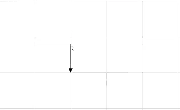
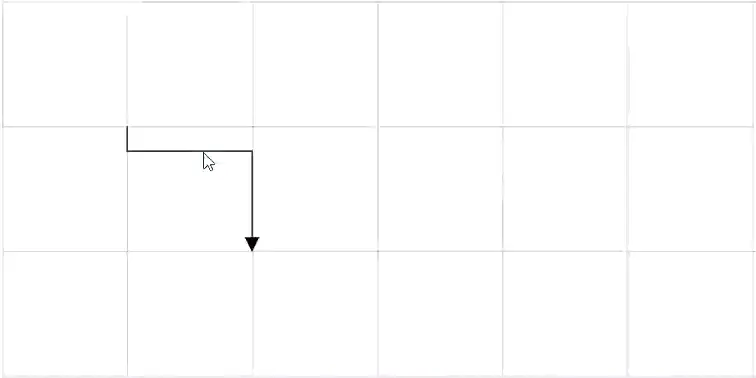
How to Drag Connector Endpoints
The connector can be selected by clicking it. When the connector is selected, circles will be added on the starting and ending of the connector that is represented by thumbs. Clicking and dragging those handles helps you to adjusts the source and target points.
@using Syncfusion.Blazor.Diagram

<SfDiagramComponent @ref="_diagram" Width="1000px" Height="500px" Connectors="@_connectors" />

@code
{
    //Reference the diagram
    private SfDiagramComponent _diagram;
    //Intialize the diagram's connector collection
    private DiagramObjectCollection<Connector> _connectors = new DiagramObjectCollection<Connector>();

    protected override void OnInitialized()
    {
        Dictionary<string, object> ConnectorInfo = new Dictionary<string, object>();
        ConnectorInfo.Add("connectorInfo", "Central Connector");
        Connector Connector = new Connector()
        {
            ID = "connector1",
            SourcePoint = new DiagramPoint()
            {
                X = 100,
                Y = 100
            },
            TargetPoint = new DiagramPoint()
            {
                X = 200,
                Y = 200
            },
            Type = ConnectorSegmentType.Orthogonal,
            TargetDecorator = new DecoratorSettings()
            {
                Shape = DecoratorShape.Circle,
                Style = new ShapeStyle()
                {
                    Fill = "red",
                    StrokeColor = "red",
                    StrokeWidth = 1
                }
            },
            SourceDecorator=new DecoratorSettings()
            {
                Shape = DecoratorShape.Circle,
                Style = new ShapeStyle()
                {
                    Fill = "red",
                    StrokeColor = "red",
                    StrokeWidth = 1
                }
            },
            AdditionalInfo = ConnectorInfo
        };
        _connectors.Add(Connector);
    }
}
A complete working sample can be downloaded from GitHub
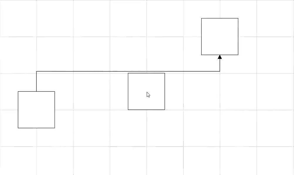
How to Route the Connectors
The connectors may overlap with adjacent nodes when a node is positioned so that it encounters the connector. This overlap can reduce the clarity of the connector’s path. To prevent this, the Routing process can be utilized.
Routing is the process of adjusting the geometry of connectors to prevent them from overlapping with any nearby nodes in their path. This feature can be activated by adding the Routing enum value to the Constraints property of diagram.
@using Syncfusion.Blazor.Diagram

<SfDiagramComponent Width="1000px" Height="500px" Connectors="@_connectors" Nodes="@_nodes" Constraints="@_diagramConstraints">
</SfDiagramComponent>

@code
{
    // Enable routing constraints for diagram.
    private DiagramConstraints _diagramConstraints = DiagramConstraints.Default | DiagramConstraints.Routing;
    // Intialize the node collection.
    private DiagramObjectCollection<Node> _nodes = new DiagramObjectCollection<Node>();
    // Intialize the connector collection.
    private DiagramObjectCollection<Connector> _connectors = new DiagramObjectCollection<Connector>();

    protected override void OnInitialized()
    {
        _nodes = new DiagramObjectCollection<Node>()
        {
            new Node() { ID = "node1", OffsetX = 100, OffsetY = 300, Width = 100, Height =100 },
            new Node() { ID = "node2", OffsetX = 600, OffsetY = 100, Width = 100, Height = 100 },
            new Node() { ID = "node3", OffsetX = 400, OffsetY = 250, Width = 100, Height = 100 }
        };
        _connectors = new DiagramObjectCollection<Connector>(){
            new Connector()
            {
                ID = "connector1",
                SourceID = "node1", TargetID = "node2",
                Type = ConnectorSegmentType.Orthogonal
            }
        };
    }

    private void OnNodeCreating(IDiagramObject obj)
    {
        if (obj is Node node)
        {
            node.Style = new ShapeStyle() { Fill = "#6BA5D7", StrokeColor = "#6BA5D7" };
        }
    }

    private void OnConnectorCreating(IDiagramObject obj)
    {
        if (obj is Connector connector)
        {
            connector.Style = new ShapeStyle() { StrokeColor = "#6BA5D7", StrokeWidth = 1 };
            connector.TargetDecorator = new DecoratorSettings()
            {
                Shape = DecoratorShape.Arrow,
                Style = new ShapeStyle() { Fill = "#6BA5D7", StrokeColor = "#6BA5D7", StrokeWidth = 1 }
            };
        }
    }
}
A complete working sample can be downloaded from GitHub.
Note: Routing is applicable only for orthogonal connectors.
Routing Types
Determines the routing strategy used for connectors in the diagram. It can be set to either Classic for faster routing or Advanced for more accurate routing with better obstacle avoidance. The routing algorithm can be specified by using RoutingType property of LineRoutingSettings class.
Classic Routing
The Classic routing algorithm adds additional segments based on the position and dimensions of the obstacles in the path. This routing method prioritizes reducing the impact of obstacles over minimizing the geometry length and the number of bends. Use Classic routing when it’s crucial to navigate around obstacles efficiently, even if it means having a longer path or more bends.
@using Syncfusion.Blazor.Diagram

<SfDiagramComponent Width="1000px" Height="500px" Connectors="@_connectors" Nodes="@_nodes" Constraints="@diagramConstraints">
    <LineRoutingSettings RoutingType="@routingTypes"></LineRoutingSettings>
</SfDiagramComponent>

@code
{
    // Set the type of the routing
    private RoutingTypes routingTypes = RoutingTypes.Classic;
    // Enable routing constraints for diagram.
    private DiagramConstraints diagramConstraints = DiagramConstraints.Default | DiagramConstraints.Routing;
    // Intialize the node collection.
    private DiagramObjectCollection<Node> _nodes = new DiagramObjectCollection<Node>();
    // Intialize the connector collection.
    private DiagramObjectCollection<Connector> _connectors = new DiagramObjectCollection<Connector>();

    protected override void OnInitialized()
    {
        _nodes = new DiagramObjectCollection<Node>()
        {
            new Node() { ID = "node1", OffsetX = 100, OffsetY = 300, Width = 100, Height =100 },
            new Node() { ID = "node2", OffsetX = 600, OffsetY = 100, Width = 100, Height = 100 },
            new Node() { ID = "node3", OffsetX = 400, OffsetY = 250, Width = 100, Height = 100 }
        };
        _connectors = new DiagramObjectCollection<Connector>(){
            new Connector()
            {
                ID = "connector1",
                SourceID = "node1", TargetID = "node2",
                Type = ConnectorSegmentType.Orthogonal
            }
        };
    }
}A complete working sample can be downloaded from GitHub
Advanced Routing
The Advanced routing algorithm evaluates all possible geometrical paths for a connector, aiming to find the one with the minimal bends and the shortest length. Use Advanced routing when you need a more optimized path with the fewest bends and the shortest possible length, even if it means the path might get closer to obstacles.
@using Syncfusion.Blazor.Diagram

<SfDiagramComponent Width="1000px" Height="500px" Connectors="@_connectors" Nodes="@_nodes" Constraints="@_diagramConstraints">
    <LineRoutingSettings RoutingType="@_routingtypes" ObstaclePadding="@_padding"></LineRoutingSettings>
</SfDiagramComponent>

@code
{
    // Set the type of the routing
    private RoutingTypes _routingtypes = RoutingTypes.Advanced;
    // Set the padding for the obstable
    private double _padding = 20;
    // Enable routing constraints for diagram.
    private DiagramConstraints _diagramConstraints = DiagramConstraints.Default | DiagramConstraints.Routing;
    // Intialize the node collection.
    private DiagramObjectCollection<Node> _nodes = new DiagramObjectCollection<Node>();
    // Intialize the connector collection.
    private DiagramObjectCollection<Connector> _connectors = new DiagramObjectCollection<Connector>();

    protected override void OnInitialized()
    {
        _nodes = new DiagramObjectCollection<Node>()
        {
            new Node() { ID = "node1", OffsetX = 100, OffsetY = 300, Width = 100, Height =100 },
            new Node() { ID = "node2", OffsetX = 600, OffsetY = 100, Width = 100, Height = 100 },
            new Node() { ID = "node3", OffsetX = 400, OffsetY = 250, Width = 100, Height = 100 }
        };
        _connectors = new DiagramObjectCollection<Connector>(){
            new Connector()
            {
                ID = "connector1",
                SourceID = "node1", TargetID = "node2",
                Type = ConnectorSegmentType.Orthogonal
            }
        };
    }
}A complete working sample can be downloaded from GitHub
Note: The default value of RoutingType is Classic.
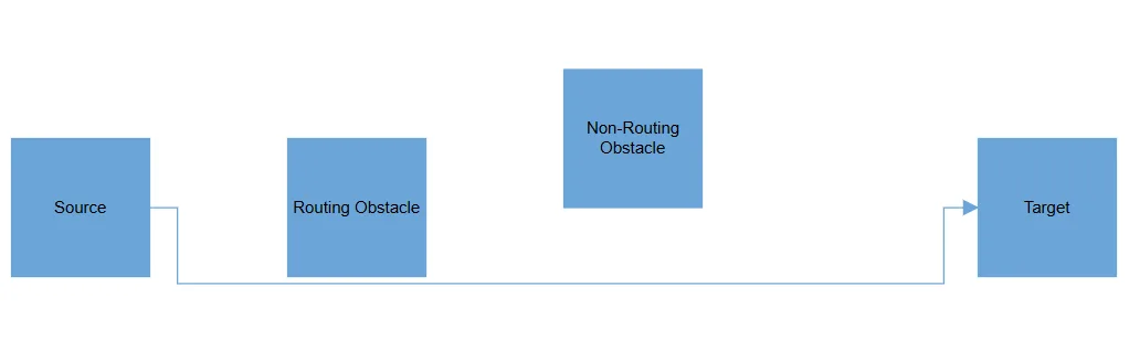
How to Enable or Disable Node Routing
By default, connectors treat all nodes as obstacles, causing connections to navigate around the node boundaries. However, you can disable this behavior and allow connectors to ignore the node as an obstacle by removing the RoutingObstacle from the node’s Constraints property.
@using Syncfusion.Blazor.Diagram

<SfDiagramComponent Width="1000px" Height="500px" NodeCreating="@OnNodeCreating" ConnectorCreating="@OnConnectorCreating" Connectors="@_connectors" Nodes="@_nodes" Constraints="@_diagramConstraints">
    <SnapSettings Constraints="SnapConstraints.None"></SnapSettings>
</SfDiagramComponent>
@code
{
    // Enable routing constraints for the diagram.
    private DiagramConstraints _diagramConstraints = DiagramConstraints.Default | DiagramConstraints.Routing;
    // Intialize the node collection.
    private DiagramObjectCollection<Node> _nodes = new DiagramObjectCollection<Node>();
    // Intialize the connector collection.
    private DiagramObjectCollection<Connector> _connectors = new DiagramObjectCollection<Connector>();
    protected override void OnInitialized()
    {
        _nodes = new DiagramObjectCollection<Node>()
        {
            new Node()
            {
                ID = "Source",
                OffsetX = 100,
                OffsetY = 300,
                Width = 100,
                Height =100,
                Annotations = new DiagramObjectCollection<ShapeAnnotation>()
                {
                    new ShapeAnnotation()
                    {
                        Content="Source"
                    }
                },
                Ports = new DiagramObjectCollection<PointPort>()
                {
                    new PointPort()
                    {
                        ID="port1",
                        Offset=new DiagramPoint() { X = 1, Y = 0.5 }
                    }
                }
            },
            new Node()
            {
                ID = "Target",
                OffsetX = 800,
                OffsetY = 300,
                Width = 100,
                Height = 100,
                Annotations = new DiagramObjectCollection<ShapeAnnotation>()
                {
                    new ShapeAnnotation()
                    {
                        Content="Target"
                    }
                },
                Ports = new DiagramObjectCollection<PointPort>()
                {
                    new PointPort()
                    {
                        ID="port1",
                        Offset = new DiagramPoint()
                        { X = 0, Y = 0.5 }
                    }
                }
            },
            new Node()
            {
                ID = "RoutingObstacle",
                OffsetX = 300,
                OffsetY = 300,
                Width = 100,
                Height = 100,
                Annotations= new DiagramObjectCollection<ShapeAnnotation>()
                {
                    new ShapeAnnotation()
                    {
                        Content="Routing Obstacle"
                    }
                },
            },
            new Node()
            {
                ID = "NonRoutingObstacle",
                OffsetX = 500,
                OffsetY = 250,
                Width = 100,
                Height = 100,
                Annotations= new DiagramObjectCollection<ShapeAnnotation>()
                {
                    new ShapeAnnotation()
                    {
                        Content="Non-Routing Obstacle"
                    }
                }, Constraints = NodeConstraints.Default & ~NodeConstraints.RoutingObstacle
            }
        };
        _connectors = new DiagramObjectCollection<Connector>(){
            new Connector()
            {
                ID = "connector1",
                SourceID = "Source", TargetID = "Target", SourcePortID="port1", TargetPortID="port1",
                Type = ConnectorSegmentType.Orthogonal
            }
        };
    }
    private void OnNodeCreating(IDiagramObject obj)
    {
        if (obj is Node node)
        {
            node.Style = new ShapeStyle() { Fill = "#6BA5D7", StrokeColor = "#6BA5D7" };
        }
    }
    private void OnConnectorCreating(IDiagramObject obj)
    {
        if (obj is Connector connector)
        {
            connector.Style = new ShapeStyle() { StrokeColor = "#6BA5D7", StrokeWidth = 1 };
            connector.TargetDecorator = new DecoratorSettings()
                {
                    Shape = DecoratorShape.Arrow,
                    Style = new ShapeStyle() { Fill = "#6BA5D7", StrokeColor = "#6BA5D7", StrokeWidth = 1 }
                };
        }
    }
}
A complete working sample can be downloaded from GitHub.
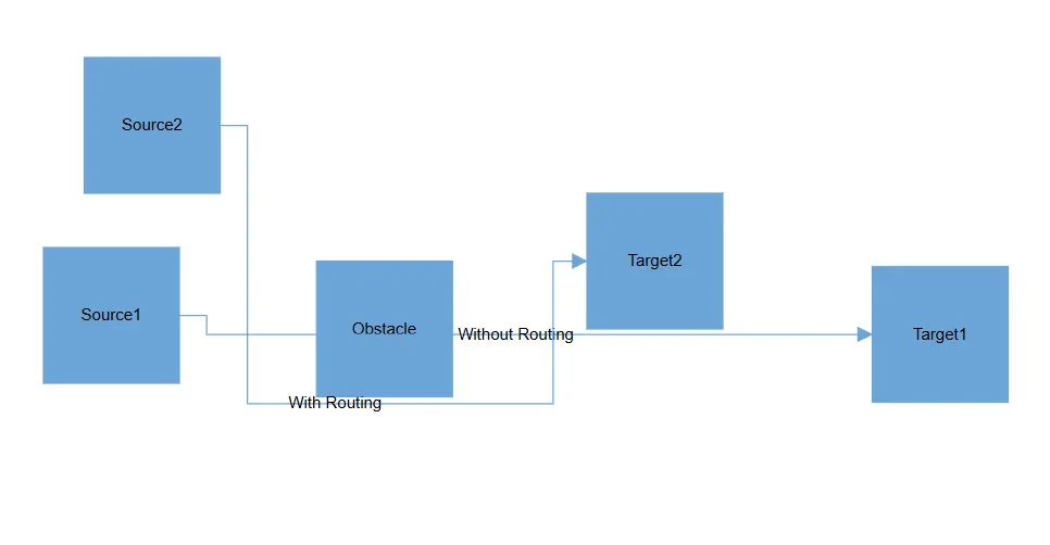
How to Enable or Disable Connector Routing
By default, connector routing behavior is inherited based on the value of the diagram’s Constraints property. If you wish to independently control the routing of a specific connector regardless of the diagram settings, you can achieve this by removing the InheritRouting enum value from the connector’s Constraints property. Then, add the Routing enum value to enable routing or remove it to disable routing altogether.
@using Syncfusion.Blazor.Diagram

<SfDiagramComponent Width="1000px" Height="500px" NodeCreating="@OnNodeCreating" ConnectorCreating="@OnConnectorCreating" Connectors="@_connectors" Nodes="@_nodes" Constraints="@_diagramConstraints">
    <SnapSettings Constraints="SnapConstraints.None"></SnapSettings>
</SfDiagramComponent>

@code
{
    // Enable routing constraints for the diagram.
    private DiagramConstraints _diagramConstraints = DiagramConstraints.Default | DiagramConstraints.Routing;
    //Intialize the node collection
    private DiagramObjectCollection<Node> _nodes = new DiagramObjectCollection<Node>();
    //Intialize the connector collection
    private DiagramObjectCollection<Connector> _connectors = new DiagramObjectCollection<Connector>();

    protected override void OnInitialized()
    {
        _nodes = new DiagramObjectCollection<Node>()
        {
            new Node()
            {
                ID = "Source",
                OffsetX = 90,
                OffsetY = 290,
                Width = 100,
                Height =100,
                Annotations= new DiagramObjectCollection<ShapeAnnotation>()
                {
                    new ShapeAnnotation()
                    {
                        Content="Source1"
                    }
                },
                Ports=new DiagramObjectCollection<PointPort>()
                {
                    new PointPort()
                    {
                        ID="port1",
                        Offset=new DiagramPoint() { X = 1, Y = 0.5 }
                    }
                }
            },
            new Node()
            {
                ID = "Target",
                OffsetX = 700,
                OffsetY = 304,
                Width = 100,
                Height = 100,
                Annotations= new DiagramObjectCollection<ShapeAnnotation>()
                {
                    new ShapeAnnotation()
                    {
                        Content="Target1"
                    }
                },
                Ports = new DiagramObjectCollection<PointPort>()
                {
                    new PointPort()
                    {
                        ID="port1",
                        Offset=new DiagramPoint() { X = 0, Y = 0.5 }
                    }
                }
            },
            new Node()
            {
                ID = "Source2",
                OffsetX = 120,
                OffsetY = 150,
                Width = 100,
                Height = 100,
                Annotations= new DiagramObjectCollection<ShapeAnnotation>()
                {
                    new ShapeAnnotation()
                    {
                        Content="Source2"
                    }
                },
            },
            new Node()
            {
                ID = "Target2",
                OffsetX = 490,
                OffsetY = 250,
                Width = 100,
                Height = 100,
                Annotations= new DiagramObjectCollection<ShapeAnnotation>()
                {
                    new ShapeAnnotation()
                    {
                        Content="Target2"
                    }
                }
            },
            new Node()
            {
                ID = "Obstacle",
                OffsetX = 291,
                OffsetY = 300,
                Width = 100,
                Height = 100,
                Annotations= new DiagramObjectCollection<ShapeAnnotation>()
                {
                    new ShapeAnnotation()
                    {
                        Content="Obstacle"
                    }
                },
            },
        };
        _connectors = new DiagramObjectCollection<Connector>(){
            new Connector()
            {
                ID = "connector1",
                SourceID = "Source", TargetID = "Target",
                Type = ConnectorSegmentType.Orthogonal,
                // Disable the inherit routing for the connector
                Constraints = ConnectorConstraints.Default & ~ConnectorConstraints.InheritRouting,
                Annotations = new DiagramObjectCollection<PathAnnotation>(){ new PathAnnotation(){ Content = "Without Routing" } }
            },
            new Connector()
            {
                ID = "connector2",
                SourceID = "Source2", TargetID = "Target2",
                Type = ConnectorSegmentType.Orthogonal,
                // Enable the routing for the connector
                Constraints = (ConnectorConstraints.Default & ~ConnectorConstraints.InheritRouting) | ConnectorConstraints.Routing,
                Annotations = new DiagramObjectCollection<PathAnnotation>(){ new PathAnnotation(){ Content = "With Routing" } }
            }
        };
    }

    private void OnNodeCreating(IDiagramObject obj)
    {
        if (obj is Node node)
        {
            node.Style = new ShapeStyle() { Fill = "#6BA5D7", StrokeColor = "#6BA5D7" };
        }
    }

    private void OnConnectorCreating(IDiagramObject obj)
    {
        if (obj is Connector connector)
        {
            connector.Style = new ShapeStyle() { StrokeColor = "#6BA5D7", StrokeWidth = 1 };
            connector.TargetDecorator = new DecoratorSettings()
            {
                Shape = DecoratorShape.Arrow,
                Style = new ShapeStyle() { Fill = "#6BA5D7", StrokeColor = "#6BA5D7", StrokeWidth = 1 }
            };
        }
    }
}
A complete working sample can be downloaded from GitHub.
How to Define Distance Between Nodes and Connectors
The ObstaclePadding property defines the minimum distance between connectors and obstacles when Advanced routing is enabled. This ensures connectors are routed with clear spacing around obstacles for improved readability.
@using Syncfusion.Blazor.Diagram

<SfDiagramComponent Width="1000px" Height="500px" Connectors="@_connectors" Nodes="@_nodes" Constraints="@_diagramConstraints">
    <LineRoutingSettings RoutingType="@_routingTypes" ObstaclePadding="@_padding"></LineRoutingSettings>
</SfDiagramComponent>

@code
{
    // Set the type of the routing
    private RoutingTypes _routingTypes = RoutingTypes.Advanced;
    // Set the padding for the obstable
    private double _padding = 12;
    // Enable routing constraints for diagram.
    private DiagramConstraints _diagramConstraints = DiagramConstraints.Default | DiagramConstraints.Routing;
    // Intialize the node collection.
    private DiagramObjectCollection<Node> _nodes = new DiagramObjectCollection<Node>();
    // Intialize the connector collection.
    private DiagramObjectCollection<Connector> _connectors = new DiagramObjectCollection<Connector>();

    protected override void OnInitialized()
    {
        _nodes = new DiagramObjectCollection<Node>()
        {
            new Node()
            {
                ID = "node1",
                OffsetX = 100,
                OffsetY = 300,
                Width = 100,
                Height =100,
                Annotations= new DiagramObjectCollection<ShapeAnnotation>()
                {
                    new ShapeAnnotation()
                    {
                        Content="Source"
                    }
                }
            },
            new Node()
            {
                ID = "node2",
                OffsetX = 430,
                OffsetY = 130,
                Width = 100,
                Height = 100,
                Annotations= new DiagramObjectCollection<ShapeAnnotation>()
                {
                    new ShapeAnnotation()
                    {
                        Content="Target"
                    }
                }
            },
            new Node()
            {
                ID = "node3",
                OffsetX = 430,
                OffsetY = 250,
                Width = 100,
                Height = 100,
                Annotations= new DiagramObjectCollection<ShapeAnnotation>()
                {
                    new ShapeAnnotation()
                    {
                        Content="Obstacle 1"
                    }
                }
            },
            new Node()
            {
                ID = "node4",
                OffsetX = 150,
                OffsetY = 90,
                Width = 100,
                Height = 100,
                Annotations= new DiagramObjectCollection<ShapeAnnotation>()
                {
                    new ShapeAnnotation()
                    {
                        Content="Obstacle 2"
                    }
                }
            }
        };
        _connectors = new DiagramObjectCollection<Connector>(){
            new Connector()
            {
                ID = "connector1",
                SourceID = "node1", TargetID = "node2",
                Type = ConnectorSegmentType.Orthogonal
            }
        };
    }
}A complete working sample can be downloaded from GitHub
The following table shows the various obstacle padding.
| ObstaclePadding values | Output |
|---|---|
| 12 | 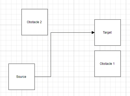 |
| 20 | 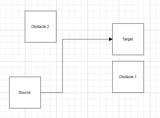 |
Note: ObstaclePadding property is only applicable when the RoutingType property is set to [RoutingTypes.Advanced]. Default value of ObstaclePadding is 12.
How to Avoid Line Overlapping
The diagram can prevent connectors from overlapping to enhance clarity and readability. This feature intelligently adjusts connector paths to minimise stacking orthogonal connectors on top of each other, reducing visual clutter and enhancing diagram structure. It is especially useful in complex diagrams with multiple orthogonal connectors, where overlapping lines can make interpretation difficult.
Enable this behavior by adding the AvoidLineOverlapping enum value to the Constraints property.
@using Syncfusion.Blazor
@using Syncfusion.Blazor.Diagram
<SfDiagramComponent @ref="_diagram" Height="700px" Width="100%" @bind-Nodes="@_nodes" LineRoutingSettings="@_lineRoutingSettings" @bind-Connectors="@_connectors" Constraints="@_diagramConstraints">
</SfDiagramComponent>

@code {
    private SfDiagramComponent _diagram;
    private DiagramObjectCollection<Node> _nodes = new DiagramObjectCollection<Node>();
    private DiagramObjectCollection<Connector> _connectors = new DiagramObjectCollection<Connector>();
    DiagramConstraints _diagramConstraints = DiagramConstraints.Default | DiagramConstraints.Routing | DiagramConstraints.AvoidLineOverlapping;
    LineRoutingSettings _lineRoutingSettings = new LineRoutingSettings()
    {
        RoutingType = RoutingTypes.Classic
    };
}
The Avoid Connector Overlapping behavior ensures connectors do not visually overlap within the viewport, improving readability and reducing visual clutter.
Viewport-Based Resolution: Overlaps are resolved only for connectors visible in the current viewport. As you scroll through the diagram, additional connectors will automatically adjusted to avoid overlapping once they come into view.
Overview Behavior: In the Overview panel, connectors outside the current viewport may initially appear overlapped. These will also be resolved dynamically as the corresponding area comes into focus in the main diagram view.
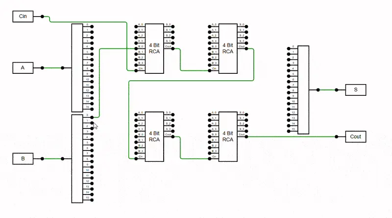
The following example demonstrates enabling the AvoidLineOverlapping feature in the diagram.
@using Syncfusion.Blazor
@using Syncfusion.Blazor.Diagram

<SfDiagramComponent @ref="_diagram" Height="700px" Width="100%" @bind-Nodes="@_nodes" LineRoutingSettings="@_lineRoutingSettings" @bind-Connectors="@_connectors" Constraints="@_diagramConstraints" />

@code
{
    private SfDiagramComponent _diagram;
    private DiagramObjectCollection<Node> _nodes = new DiagramObjectCollection<Node>();
    private DiagramObjectCollection<Connector> _connectors = new DiagramObjectCollection<Connector>();
    private DiagramConstraints _diagramConstraints = DiagramConstraints.Default | DiagramConstraints.Routing | DiagramConstraints.AvoidLineOverlapping;
    private LineRoutingSettings _lineRoutingSettings= new LineRoutingSettings() { RoutingType = RoutingTypes.Classic };

    protected override void OnInitialized()
    {
        InitDiagramModel();
    }

    private void InitDiagramModel()
    {
        Create1To16Node("node1", 205, 180, 80, 240);
        Create1To16Node("node2", 205, 427.5, 80, 240);
        Create9To5Node("node3", 415, 127.5, 100, 135);
        Create9To5Node("node4", 415, 367.5, 100, 135);
        Create9To5Node("node5", 615, 127.5, 100, 135);
        Create9To5Node("node6", 615, 367.5, 100, 135);
        Create16To1Node("node7", 820, 240, 80, 240);
        CreateInputNode("node8", 70, 40, 80, 30, "Cin");
        CreateInputNode("node9", 70, 180, 80, 30, "A");
        CreateInputNode("node10", 70, 427.5, 80, 30, "B");
        CreateOutputNode("node11", 950, 240, 80, 30, "S");
        CreateOutputNode("node12", 950, 367.5, 80, 30, "Cout");
        CreateConnector("connector01", "node8", "node3", 0, 8, "lightGreen");
        CreateConnector("connector02", "node9", "node1", 0, 0, "orange");
        CreateConnector("connector03", "node10", "node2", 0, 0, "orange");
        CreateConnector("connector04", "node7", "node11", 0, 0, "orange");
        CreateConnector("connector05", "node6", "node12", 4, 0);
        CreateConnector("connector06", "node3", "node5", 4, 8);
        CreateConnector("connector07", "node5", "node4", 4, 8, "lightGreen");
        CreateConnector("connector08", "node4", "node6", 4, 8);
        CreateConnector("connector1", "node1", "node3", 0, 0);
        CreateConnector("connector2", "node1", "node3", 1, 1);
        CreateConnector("connector3", "node1", "node3", 2, 2);
        CreateConnector("connector4", "node1", "node3", 3, 3);
        CreateConnector("connector5", "node1", "node5", 4, 0, "lightGreen");
        CreateConnector("connector6", "node1", "node5", 5, 1);
        CreateConnector("connector7", "node1", "node5", 6, 2);
        CreateConnector("connector8", "node1", "node5", 7, 3, "lightGreen");
        CreateConnector("connector9", "node1", "node4", 8, 0, "lightGreen");
        CreateConnector("connector10", "node1", "node4", 9, 1, "lightGreen");
        CreateConnector("connector11", "node1", "node4", 10, 2);
        CreateConnector("connector12", "node1", "node4", 11, 3, "lightGreen");
        CreateConnector("connector13", "node1", "node6", 12, 0);
        CreateConnector("connector14", "node1", "node6", 13, 1, "lightGreen");
        CreateConnector("connector15", "node1", "node6", 14, 2, "lightGreen");
        CreateConnector("connector16", "node1", "node6", 15, 3);
        CreateConnector("connector17", "node2", "node3", 0, 4, "lightGreen");
        CreateConnector("connector18", "node2", "node3", 1, 5, "lightGreen");
        CreateConnector("connector19", "node2", "node3", 2, 6);
        CreateConnector("connector20", "node2", "node3", 3, 7);
        CreateConnector("connector25", "node2", "node4", 8, 4);
        CreateConnector("connector26", "node2", "node4", 9, 5, "lightGreen");
        CreateConnector("connector27", "node2", "node4", 10, 6);
        CreateConnector("connector28", "node2", "node4", 11, 7);
        CreateConnector("connector24", "node2", "node5", 7, 7, "lightGreen");
        CreateConnector("connector23", "node2", "node5", 6, 6, "lightGreen");
        CreateConnector("connector22", "node2", "node5", 5, 5, "lightGreen");
        CreateConnector("connector21", "node2", "node5", 4, 4, "lightGreen");
        CreateConnector("connector29", "node2", "node6", 12, 4, "lightGreen");
        CreateConnector("connector30", "node2", "node6", 13, 5);
        CreateConnector("connector31", "node2", "node6", 14, 6);
        CreateConnector("connector32", "node2", "node6", 15, 7);
        CreateConnector("connector33", "node3", "node7", 0, 0);
        CreateConnector("connector34", "node3", "node7", 1, 1);
        CreateConnector("connector35", "node3", "node7", 2, 2, "lightGreen");
        CreateConnector("connector36", "node3", "node7", 3, 3);
        CreateConnector("connector37", "node5", "node7", 0, 4);
        CreateConnector("connector38", "node5", "node7", 1, 5);
        CreateConnector("connector39", "node5", "node7", 2, 6);
        CreateConnector("connector40", "node5", "node7", 3, 7, "lightGreen");
        CreateConnector("connector41", "node4", "node7", 0, 8);
        CreateConnector("connector42", "node4", "node7", 1, 9);
        CreateConnector("connector43", "node4", "node7", 2, 10, "lightGreen");
        CreateConnector("connector44", "node4", "node7", 3, 11);
        CreateConnector("connector45", "node6", "node7", 0, 12);
        CreateConnector("connector46", "node6", "node7", 1, 13);
        CreateConnector("connector47", "node6", "node7", 2, 14);
        CreateConnector("connector48", "node6", "node7", 3, 15, "lightGreen");
    }

    private void Create1To16Node(string id, double x, double y, double width, double height)
    {
        Node node = CreateNode(id, x, y, width, height);
        AddShape(node, 1, 16);

        DiagramObjectCollection<PointPort> inPorts = AddPorts(node, 1, "in");
        DiagramObjectCollection<PointPort> outPorts = AddPorts(node, 16, "out");

        AddPortsLabels(node, 16, "out");
    }

    private void Create16To1Node(string id, double x, double y, double width, double height)
    {
        Node node = CreateNode(id, x, y, width, height);
        AddShape(node, 16, 1);

        DiagramObjectCollection<PointPort> inPorts = AddPorts(node, 16, "in");
        DiagramObjectCollection<PointPort> outPorts = AddPorts(node, 1, "out");

        AddPortsLabels(node, 16, "in");
    }

    private void Create9To5Node(string id, double x, double y, double width, double height)
    {
        List<string> leftLabels = new List<string> { "A_0", "A_1", "A_2", "A_3", "B_0", "B_1", "B_2", "B_3", "Cin" };
        List<string> rightLabels = new List<string> { "S_0", "S_1", "S_2", "S_3", "Cout" };

        Node node = CreateNode(id, x, y, width, height, "4 Bit\nRCA");
        AddShape(node, 9, 5);

        DiagramObjectCollection<PointPort> inPorts = AddPorts(node, 9, "in");
        DiagramObjectCollection<PointPort> outPorts = AddPorts(node, 5, "out", 9);

        AddPortsLabels(node, 9, "in", leftLabels);
        AddPortsLabels(node, 5, "out", rightLabels, 9);
    }

    private void CreateInputNode(string id, double x, double y, double width, double height, string label)
    {
        Node node = CreateNode(id, x, y, width, height, label);
        AddShape(node, 0, 1);

        DiagramObjectCollection<PointPort> outPorts = AddPorts(node, 1, "out");

        if (node.Annotations.Count > 0)
        {
            ShapeAnnotation annotation = node.Annotations[0];
            annotation.Offset = new DiagramPoint
            {
                X = (width - 25) / (2 * width),
                Y = 0.5
            };
        }
    }

    private void CreateOutputNode(string id, double x, double y, double width, double height, string label)
    {
        Node node = CreateNode(id, x, y, width, height, label);
        AddShape(node, 1, 0);

        DiagramObjectCollection<PointPort> inPorts = AddPorts(node, 1, "in");

        if (node.Annotations.Count > 0)
        {
            ShapeAnnotation annotation = node.Annotations[0];
            annotation.Offset = new DiagramPoint
            {
                X = 1 - ((width - 25) / (2 * width)),
                Y = 0.5
            };
        }
    }

    private void AddShape(Node node, int inCount, int outCount)
    {
        int maxCount = Math.Max(inCount, outCount);
        double? rightX = outCount == 0 ? node.Width : node.Width - 25;
        string pathData = $"M {rightX} 0 ";

        if (outCount > 1)
        {
            for (int i = 1; i <= outCount; i++)
            {
                double? portY = ((i / (double)maxCount) - (1 / (2.0 * maxCount))) * node.Height;
                pathData += $"L {rightX} {portY} L {node.Width} {portY} L {rightX} {portY} ";
            }
        }
        else if (outCount == 1)
        {
            pathData += $"L {rightX} {node.Height * 0.5} L {node.Width} {node.Height * 0.5} L {rightX} {node.Height * 0.5} ";
        }

        double leftX = inCount == 0 ? 0 : 25;
        pathData += $"L {rightX} {node.Height} L {leftX} {node.Height} ";

        if (inCount > 1)
        {
            for (int i = inCount; i >= 1; i--)
            {
                double? portY = ((i / (double)maxCount) - (1 / (2.0 * maxCount))) * node.Height;
                pathData += $"L {leftX} {portY} L 0 {portY} L {leftX} {portY} ";
            }
        }
        else if (inCount == 1)
        {
            pathData += $"L {leftX} {node.Height * 0.5} L 0 {node.Height * 0.5} L {leftX} {node.Height * 0.5} ";
        }

        pathData += $"L {leftX} 0 Z";
        node.Shape = new PathShape { Type = NodeShapes.Path, Data = pathData };
    }

    private DiagramObjectCollection<PointPort> AddPorts(Node node, int count, string side, double factor = 0)
    {
        if (factor == 0)
        {
            factor = count;
        }

        DiagramObjectCollection<PointPort> ports = new DiagramObjectCollection<PointPort>();

        if (count > 1)
        {
            for (int i = 1; i <= count; i++)
            {
                PointPort port = new PointPort
                {
                    ID = $"{node.ID}{side}{i - 1}",
                    Offset = new DiagramPoint
                    {
                        X = side == "out" ? 1 : 0,
                        Y = (i / (double)factor) - (1 / (2.0 * factor))
                    },
                    Visibility = PortVisibility.Visible,
                    Shape = PortShapes.Circle,
                    Style = new ShapeStyle { Fill = "black" },
                    Width = 8,
                    Height = 8
                };
                node.Ports.Add(port);
            }
        }
        else
        {
            PointPort port = new PointPort
            {
                ID = $"{node.ID}{side}0",
                Offset = new DiagramPoint
                {
                    X = side == "out" ? 1 : 0,
                    Y = 0.5
                },
                Visibility = PortVisibility.Visible,
                Shape = PortShapes.Circle,
                Style = new ShapeStyle { Fill = "black" },
                Width = 8,
                Height = 8,
            };
            node.Ports.Add(port);
        }
        return ports;
    }

    private void AddPortsLabels(Node node, int count, string side, List<string> labels = null, double factor = 0)
    {
        if (factor == 0)
        {
            factor = count;
        }

        DiagramObjectCollection<ShapeAnnotation> annotations = new DiagramObjectCollection<ShapeAnnotation>();
        double width = node.Width ?? 0.0; // Provide a default value to avoid null
        double x = side == "out" ? (width - 25 * 0.5) / width : (25 * 0.5) / width;

        for (int i = 1; i <= count; i++)
        {
            ShapeAnnotation label = new ShapeAnnotation
            {
                Content = labels != null ? labels[i - 1] : $"{i - 1}",
                Offset = new DiagramPoint
                {
                    X = x,
                    Y = (i / (double)factor) - (1 / (2.0 * factor))
                },
                Style = new TextStyle { FontSize = 7 },
                VerticalAlignment = VerticalAlignment.Bottom,
                Margin = new DiagramThickness { Bottom = 2 }
            };
            node.Annotations.Add(label);
        }
    }

    private Node CreateNode(string id, double x, double y, double width, double height, string label = null)
    {
        ShapeStyle shapeStyle = new ShapeStyle { StrokeColor = "black", StrokeWidth = 2 };

        Node diagramNode = new Node
        {
            ID = id,
            OffsetX = x,
            OffsetY = y,
            Width = width,
            Height = height,
            Style = shapeStyle,
            Shape = new BasicShape { Type = NodeShapes.Basic },
        };

        if (!string.IsNullOrEmpty(label))
        {
            ShapeAnnotation annotation = new ShapeAnnotation
            {
                Content = label,
                Style = new TextStyle { FontSize = 14 }
            };
            diagramNode.Annotations.Add(annotation);
        }

        _nodes.Add(diagramNode);
        return diagramNode;
    }

    private void CreateConnector(string id, string sourceId, string targetId, int sourcePortIndex, int targetPortIndex, string strokeColor = null)
    {
        string color = !string.IsNullOrEmpty(strokeColor) ? strokeColor : "green";

        if (color == "lightGreen")
        {
            color = "#1AD81A";
        }
        else if (color == "green")
        {
            color = "#005100";
        }

        Connector diagramConnector = new Connector
        {
            ID = id,
            CornerRadius = 5,
            SourceID = sourceId,
            TargetID = targetId,
            SourcePortID = sourceId + "out" + sourcePortIndex,
            TargetPortID = targetId + "in" + targetPortIndex,
            Type = ConnectorSegmentType.Orthogonal,
            Style = new ShapeStyle { StrokeColor = color, StrokeWidth = 2 },
            TargetDecorator = new DecoratorSettings { Shape = DecoratorShape.None }
        };
        _connectors.Add(diagramConnector);
    }
}A complete working sample can be downloaded from GitHub.
Note: Overlaps are resolved only for connectors visible in the viewport. The rest will be resolved as they are scrolled into view. The same applies to the overview, where connectors outside the viewport will appear overlapped and will resolve when focused within the viewport.
How to Flip a Connector
The Flip is performed to give the mirrored image of the original element.
For more information, refer to Connector Flip.