Segments in Blazor Diagram Component
13 Sep 202321 minutes to read
The path of the connector is defined with a collection of segments. There are three types of segments.
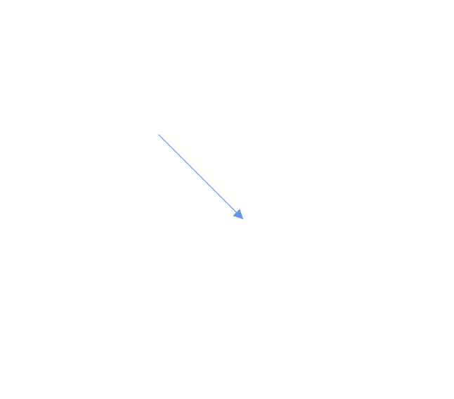
How to create straight segment
To create a straight line, specify the Type of the segment as Straight and add a straight segment to Segments collection and need to specify Type for the connector. The following code example illustrates how to create a default straight segment.
@using Syncfusion.Blazor.Diagram

<SfDiagramComponent Width="1000px" Height="500px" Connectors="@connectors">
</SfDiagramComponent>

@code
{
    //Defines diagram's connector collection.
    DiagramObjectCollection<Connector> connectors = new DiagramObjectCollection<Connector>();

    protected override void OnInitialized()
    {
        Connector Connector = new Connector()
        {
            ID = "connector1",
            SourcePoint = new DiagramPoint()
            {
                X = 100,
                Y = 100
            },
            Style = new ShapeStyle() { StrokeColor = "#6f409f", StrokeWidth = 1 },
            TargetPoint = new DiagramPoint() { X = 200, Y = 200 },
             //Specify the segment type as straight.
            Type = ConnectorSegmentType.Straight,
            TargetDecorator = new DecoratorSettings()
            {
                Shape = DecoratorShape.Arrow,
                Style = new ShapeStyle()
                {
                    Fill = "#6f409f",
                    StrokeColor = "#6f409f",
                    StrokeWidth = 1
                }
            }
        };
        connectors.Add(Connector);
    }
}
You can download a complete working sample from GitHub
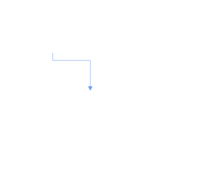
How to create orthogonal segment
Orthogonal segments are used to create segments that are perpendicular to each other. Set the segment Type as Orthogonal to create a default orthogonal segment and need to specify Type. The following code example illustrates how to create a default orthogonal segment.
@using Syncfusion.Blazor.Diagram

<SfDiagramComponent Width="1000px" Height="500px" Connectors="@connectors">
</SfDiagramComponent>

@code
{
    //Defines diagram's connector collection.
    DiagramObjectCollection<Connector> connectors = new DiagramObjectCollection<Connector>();

    protected override void OnInitialized()
    {
        Connector Connector = new Connector()
        {
            ID = "connector1",
            SourcePoint = new DiagramPoint()
            {
                X = 100,
                Y = 100
            },
            Style = new ShapeStyle() { StrokeColor = "#6f409f", StrokeWidth = 1 },
            TargetPoint = new DiagramPoint() { X = 200, Y = 200 },
             //Specify the segments type as Orthogonal.
            Type = ConnectorSegmentType.Orthogonal,
            TargetDecorator = new DecoratorSettings()
            {
                Shape = DecoratorShape.Arrow,
                Style = new ShapeStyle()
                {
                    Fill = "#6f409f",
                    StrokeColor = "#6f409f",
                    StrokeWidth = 1
                }
            }
        };
        connectors.Add(Connector);
    }
}
You can download a complete working sample from GitHub
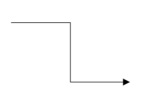
The Length and Direction properties allow to define the flow and length of segment. The following code example illustrates how to create customized orthogonal segments.
@using Syncfusion.Blazor.Diagram

<SfDiagramComponent Width="1000px" Height="500px" Connectors="@connectors">
</SfDiagramComponent>

@code
{
    //Defines diagram's connector collection.
    DiagramObjectCollection<Connector> connectors = new DiagramObjectCollection<Connector>();

    protected override void OnInitialized()
    {
        Connector Connector = new Connector()
        {
            ID = "connector1",
            SourcePoint = new DiagramPoint()
            {
                X = 100,
                Y = 100
            },
            Style = new ShapeStyle() { StrokeColor = "#6f409f", StrokeWidth = 1 },
            TargetPoint = new DiagramPoint() { X = 200, Y = 200 },
            Type = ConnectorSegmentType.Orthogonal,
            //Create a new segment with length and direction.
            Segments = new DiagramObjectCollection<ConnectorSegment>()
            {
                new OrthogonalSegment
                {
                    Length = 100,
                    Type = ConnectorSegmentType.Orthogonal,
                    Direction = Direction.Right
                },
                new OrthogonalSegment
                {
                    Length = 100,
                    Type = ConnectorSegmentType.Orthogonal,
                    Direction = Direction.Bottom,
                }
            },
            TargetDecorator = new DecoratorSettings()
            {
                Shape = DecoratorShape.Arrow,
                Style = new ShapeStyle()
                {
                    Fill = "#6f409f",
                    StrokeColor = "#6f409f",
                    StrokeWidth = 1
                }
            }
        };
        connectors.Add(Connector);
    }
}
You can download a complete working sample from GitHub
NOTE
You need to mention the segment type as same as what you mentioned in connector type. There should be no contradiction between connector type and segment type.
How to create bezier segment
Bezier segments are used to create curve segments and the curves are configurable either with the control points or with vectors. To create a bezier segment, the Type of the segment is set as Bezier and need to specify type for the connector. The following code example illustrates how to create a default bezier segment.
@using Syncfusion.Blazor.Diagram

<SfDiagramComponent Width="1000px" Height="500px" Connectors="@connectors">
</SfDiagramComponent>

@code
{
     //Defines diagram's connector collection.
    DiagramObjectCollection<Connector> connectors = new DiagramObjectCollection<Connector>();

    protected override void OnInitialized()
    {
        Connector Connector = new Connector()
        {
            ID = "connector1",
            SourcePoint = new DiagramPoint()
            {
                X = 100,
                Y = 100
            },
            Style = new ShapeStyle() { StrokeColor = "#6f409f", StrokeWidth = 1 },
            TargetPoint = new DiagramPoint() { X = 200, Y = 200 },
            Type = ConnectorSegmentType.Bezier,
            TargetDecorator = new DecoratorSettings()
            {
                Shape = DecoratorShape.Arrow,
                Style = new ShapeStyle()
                {
                    Fill = "#6f409f",
                    StrokeColor = "#6f409f",
                    StrokeWidth = 1
                }
            }
        };
        //Add the connector into connectors's collection.
        connectors.Add(Connector);
    }
}
You can download a complete working sample from GitHub

Point1 and Point2 properties are used to control the points of the bezier connector, and vector1 and Vector2 properties are used to define the length and angle between the source point and target point, respectively. The following code example illustrates how to use these properties in our control.
Connector Connector1 = new Connector()
        {
            ID = "Connector1",
            Type = ConnectorSegmentType.Bezier,
            SourcePoint = new DiagramPoint { X = 500, Y = 200 },
            TargetPoint = new DiagramPoint { X = 600, Y = 300 },
            Segments = new DiagramObjectCollection<ConnectorSegment>
            {
                new BezierSegment()
                {
                    Type = ConnectorSegmentType.Bezier,
                    //Defines the point1 and point2 for the bezier connector.
                    Point1 = new DiagramPoint { X = 500, Y = 100 },
                    Point2 = new DiagramPoint { X = 600, Y = 200 }
                }
            }
        };
         Connector Connector2 = new Connector()
         {
            ID = "Connector2",
            Type = ConnectorSegmentType.Bezier,
            SourcePoint = new DiagramPoint { X = 200, Y = 100 },
            TargetPoint = new DiagramPoint { X = 300, Y = 200 },
            Segments = new DiagramObjectCollection<ConnectorSegment>
            {
                new BezierSegment()
                {
                    Type = ConnectorSegmentType.Bezier,
                    //Defines the Vector1 and Vector2 for the bezier connector.
                    Vector1 = new Vector(){Distance = 100 ,Angle = 90 },
                    Vector2 = new Vector(){Distance = 45 ,Angle = 45 }
                }
            }
        };
You can download a complete working sample from GitHub
How to create multiple segments
Multiple segments can be defined one after another. To create a connector with multiple segments, define and add the segments to connector.Segments collection. The following code example illustrates how to create a connector with multiple segments.
@using Syncfusion.Blazor.Diagram

<SfDiagramComponent Width="1000px" Height="500px" Connectors="@connectors">
    <SnapSettings Constraints="SnapConstraints.None"></SnapSettings>
</SfDiagramComponent>

@code
{
    //Defines diagram's connector collection.
    DiagramObjectCollection<Connector> connectors = new DiagramObjectCollection<Connector>();

    protected override void OnInitialized()
    {
        Connector connector1 = new Connector()
        {
            ID = "Connector1",
            Type = ConnectorSegmentType.Orthogonal,
            SourcePoint = new DiagramPoint()
            {
                X = 100,
                Y = 100
            },
            TargetPoint = new DiagramPoint() { X = 300, Y = 200 },
            Segments = new DiagramObjectCollection<ConnectorSegment>()
            {
                new OrthogonalSegment
                {
                    Length = 100,
                    Type = ConnectorSegmentType.Orthogonal,
                    Direction = Direction.Right
                },
                new OrthogonalSegment
                {
                    Length = 100,
                    Type = ConnectorSegmentType.Orthogonal,
                    Direction = Direction.Bottom
                }
            },
        };
        //Add the connector into connectors's collection.
        connectors.Add(connector1);
    }
}
You can download a complete working sample from GitHub
- Similarly, you can create multiple segments for all the connector type.
Segment Editing
Straight segment editing
- End point of each straight segment is represented by a thumb that enables to edit the segment.
- Any number of new segments can be inserted into a straight line by clicking, when Shift and Ctrl keys are pressed (Ctrl+Shift+Click).
- Straight segments can be removed by clicking the segment end point, when Ctrl and Shift keys are pressed (Ctrl+Shift+Click).
@using Syncfusion.Blazor.Diagram

<SfDiagramComponent @ref="Diagram" Width="1000px" Height="500px" Connectors="@connectors">
</SfDiagramComponent>

@code
{
    //Reference the diagram.
    SfDiagramComponent Diagram;
    //Initialize the diagram's nodes collection
    DiagramObjectCollection<Connector> connectors = new DiagramObjectCollection<Connector>();

    protected override void OnInitialized()
    {
        Connector Connector = new Connector()
        {
            ID = "Connector1",
            Constraints = ConnectorConstraints.Default | ConnectorConstraints.DragSegmentThumb,
            SourcePoint = new DiagramPoint { X = 200, Y = 100 },
            TargetPoint = new DiagramPoint { X = 340, Y = 150 },
            // Enable the segment editing.
            Segments = new DiagramObjectCollection<ConnectorSegment>
            {
                new StraightSegment()
                {
                    Type = ConnectorSegmentType.Straight,
                    Point = new DiagramPoint { X = 300, Y = 200 }
                }
            }
        };
        connectors.Add(Connector);
    }
}
You can download a complete working sample from GitHub

Orthogonal segment editing
- Orthogonal thumbs allow you to adjust the length of adjacent segments by clicking and dragging it.
- When necessary, some segments are added or removed automatically, when dragging the segment. This is to maintain proper routing of orthogonality between segments.
@using Syncfusion.Blazor.Diagram

<SfDiagramComponent @ref="Diagram" Width="1000px"  Height="500px" Connectors="@connectors">
</SfDiagramComponent>

@code
{
    //Reference the diagram
    SfDiagramComponent Diagram;
    //Initialize the diagram's node collection.
    DiagramObjectCollection<Connector> connectors = new DiagramObjectCollection<Connector>();

    protected override void OnInitialized()
    {
        Connector Connector = new Connector()
        // Enable the segment editing.
        {
            ID = "Connector2",
            Constraints = ConnectorConstraints.Default | ConnectorConstraints.DragSegmentThumb,
            Type = ConnectorSegmentType.Orthogonal,
            SourcePoint = new DiagramPoint { X = 400, Y = 100 },
            TargetPoint = new DiagramPoint { X = 500, Y = 200 }
        };
        connectors.Add(Connector);
    }
}
You can download a complete working sample from GitHub
Bezier Segment Editing
- A segment control point of the Bezier connector is used to change the bezier vectors and points of the connector.