Mind Map Layout in Blazor Diagram Component
3 Jul 202624 minutes to read
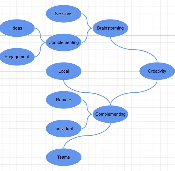
A mind map is a diagram that displays the nodes as a spider diagram organizes information around a central concept. To create a MindMap, set the layout Type to MindMap.
To see a quick walkthrough of creating a mind map layout, watch the following video:
The following code example illustrates how to create a mind map layout using a data source.
@using Syncfusion.Blazor.Diagram

<SfDiagramComponent Height="600px" NodeCreating="@OnNodeCreating" ConnectorCreating="@OnConnectorCreating">
    <DataSourceSettings ID="Id" ParentID="ParentId" DataSource="@_dataSource"></DataSourceSettings>
    <Layout Type="LayoutType.MindMap">
        <LayoutMargin Top="20" Left="20"></LayoutMargin>
    </Layout>
</SfDiagramComponent>

@code
{
    //Creates nodes with some default values.
    private void OnNodeCreating(IDiagramObject obj)
    {
        Node node = obj as Node;
        node.Height = 25;
        node.Width = 25;
        node.BackgroundColor = "#6BA5D7";
        node.Style = new ShapeStyle() { Fill = "#6495ED", StrokeWidth = 1, StrokeColor = "white" };
        node.Shape = new BasicShape() { Type = NodeShapes.Basic }; ;
    }

    //Creates connectors with some default values.
    private void OnConnectorCreating(IDiagramObject connector)
    {
        Connector connectors = connector as Connector;
        connectors.Type = ConnectorSegmentType.Bezier;
        connectors.Style = new ShapeStyle() { StrokeColor = "#6495ED", StrokeWidth = 2 };
        connectors.TargetDecorator = new DecoratorSettings
        {
            Shape = DecoratorShape.None,
        };
    }

    public class MindMapDetails
    {
        public string Id { get; set; }
        public string Label { get; set; }
        public string ParentId { get; set; }
        public string Branch { get; set; }
        public string Fill { get; set; }
    }

    private object _dataSource = new List<object>()
    {
        new MindMapDetails() { Id = "1", Label = "Creativity", ParentId = "", Branch = "Root" },
        new MindMapDetails() { Id = "2", Label = "Brainstorming", ParentId = "1", Branch = "Right" },
        new MindMapDetails() { Id = "3", Label = "Complementing", ParentId = "1", Branch = "Left" },
        new MindMapDetails() { Id = "4", Label = "Sessions", ParentId = "2", Branch = "subRight" },
        new MindMapDetails() { Id = "5", Label = "Complementing", ParentId = "2", Branch = "subRight" },
        new MindMapDetails() { Id = "6", Label = "Local", ParentId = "3", Branch = "subRight" },
        new MindMapDetails() { Id = "7", Label = "Remote", ParentId = "3", Branch = "subRight" },
        new MindMapDetails() { Id = "8", Label = "Individual", ParentId = "3", Branch = "subRight" },
        new MindMapDetails() { Id = "9", Label = "Teams", ParentId = "3", Branch = "subRight" },
        new MindMapDetails() { Id = "10", Label = "Ideas", ParentId = "5", Branch = "subRight" },
        new MindMapDetails() { Id = "11", Label = "Engagement", ParentId = "5", Branch = "subRight" },
    };
}
A complete working sample can be downloaded from GitHub
You can also control the branch for a mind map using the GetBranch method. The following example demonstrates how to configure all branches to appear on the right side using this method.
@using Syncfusion.Blazor.Diagram

<SfDiagramComponent Height="600px" NodeCreating="@OnNodeCreating" ConnectorCreating="@OnConnectorCreating">
    <DataSourceSettings ID="Id" ParentID="ParentId" DataSource="@_dataSource"></DataSourceSettings>
    <Layout Type="LayoutType.MindMap" GetBranch="@GetBranch">
        <LayoutMargin Top="20" Left="20"></LayoutMargin>
    </Layout>
</SfDiagramComponent>

@code
{
    //Set all branches on the right side for mind map layout.
    private BranchType GetBranch(IDiagramObject obj)
    {
        if ((obj as Node).ID == "1")
        {
            return BranchType.Root;
        }
        return BranchType.Right;
    }

    //Creates connectors with some default values.
    private void OnNodeCreating(IDiagramObject obj)
    {
        Node node = obj as Node;
        node.Height = 50;
        node.Width = 100;
        node.Style = new ShapeStyle() { Fill = "#6495ED", StrokeWidth = 1, StrokeColor = "white" };
        node.Shape = new BasicShape() { Type = NodeShapes.Basic, Shape = NodeBasicShapes.Ellipse };
        MindMapDetails mindMapData = node.Data as MindMapDetails;
        node.Annotations = new DiagramObjectCollection<ShapeAnnotation>()
        {
            new ShapeAnnotation()
            {
                Content = mindMapData.Label
            }
        };
    }

    //Creates node with some default values.
    private void OnConnectorCreating(IDiagramObject connector)
    {
        Connector connectors = connector as Connector;
        connectors.Type = ConnectorSegmentType.Bezier;
        connectors.Style = new TextStyle() { StrokeColor = "#6495ED", StrokeWidth = 2 };
        connectors.TargetDecorator = new DecoratorSettings
        {
            Shape = DecoratorShape.None,
        };
    }

    public class MindMapDetails
    {
        public string Id { get; set; }
        public string Label { get; set; }
        public string ParentId { get; set; }
        public string Branch { get; set; }
        public string Fill { get; set; }
    }

    private object _dataSource = new List<object>()
    {
        new MindMapDetails() { Id = "1", Label = "Creativity", ParentId = "" },
        new MindMapDetails() { Id = "2", Label = "Brainstorming", ParentId = "1" },
        new MindMapDetails() { Id = "3", Label = "Complementing", ParentId = "1" },
        new MindMapDetails() { Id = "4", Label = "Sessions", ParentId = "2" },
        new MindMapDetails() { Id = "5", Label = "Complementing", ParentId = "2" },
        new MindMapDetails() { Id = "6", Label = "Local", ParentId = "3" },
        new MindMapDetails() { Id = "7", Label = "Remote", ParentId = "3" },
        new MindMapDetails() { Id = "8", Label = "Individual", ParentId = "3" },
        new MindMapDetails() { Id = "9", Label = "Teams", ParentId = "3" },
        new MindMapDetails() { Id = "10", Label = "Ideas", ParentId = "5" },
        new MindMapDetails() { Id = "11", Label = "Engagement", ParentId = "5" },
    };
}
A complete working sample can be downloaded from GitHub
Note: In
DataSourceSettings, theIDandParentIDproperties are string, and the providedDataSourceshould have a parent-child relationship. At least one node must have an emptyParentIDto act as the root.
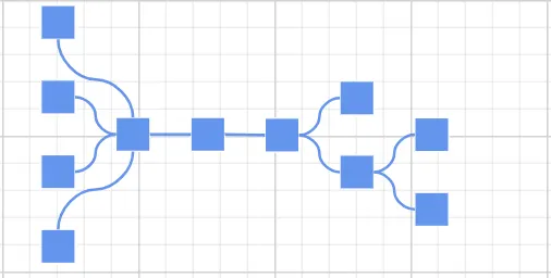
Also, you can render a mind map layout without using a Datasource. The following code demonstrates how to render a mind map layout without using DataSource.
@using Syncfusion.Blazor.Diagram

<SfDiagramComponent Height="600px" Nodes="@_nodes" Connectors="@_connectors" NodeCreating="@OnNodeCreating" ConnectorCreating="@OnConnectorCreating">
    <Layout Type="LayoutType.MindMap" Root="@_root">
        <LayoutMargin Top="20" Left="20"></LayoutMargin>
    </Layout>
</SfDiagramComponent>

@code
{
    //Initialize the diagram's nodes collection
    private DiagramObjectCollection<Node> _nodes = new DiagramObjectCollection<Node>();
    //Initialize the diagram's connectors collection
    private DiagramObjectCollection<Connector> _connectors = new DiagramObjectCollection<Connector>();
    private string _root = "node4";
    //Creates connectors with some default values.
    private void OnNodeCreating(IDiagramObject obj)
    {
        Node node = obj as Node;
        node.Height = 50;
        node.Width = 100;
        node.Style = new ShapeStyle() { Fill = "#6495ED", StrokeWidth = 1, StrokeColor = "white" };
        node.Shape = new BasicShape() { Type = NodeShapes.Basic, Shape = NodeBasicShapes.Ellipse };
    }

    //Creates node with some default values.
    private void OnConnectorCreating(IDiagramObject connector)
    {
        Connector connectors = connector as Connector;
        connectors.Type = ConnectorSegmentType.Bezier;
        connectors.Style = new TextStyle() { StrokeColor = "#6495ED", StrokeWidth = 2 };
        connectors.TargetDecorator = new DecoratorSettings
            {
                Shape = DecoratorShape.None,
            };
    }

    protected override void OnInitialized()
    {
        Node node1 = new Node()
            {
                ID = "node1",
                Width = 70,
                Height = 70,
                Ports = new DiagramObjectCollection<PointPort>()
{
                new PointPort()
                {
                    ID="left",
                    Offset = new DiagramPoint() { X = 1, Y = 0.5},
                },new PointPort()
                {
                    ID="right",
                    Offset = new DiagramPoint() { X = 0, Y = 0.5},
                }
            },
            };
        _nodes.Add(node1);
        Node node2 = new Node()
            {
                ID = "node2",
                Width = 70,
                Ports = new DiagramObjectCollection<PointPort>()
{
                new PointPort()
                {
                    ID="left",
                    Offset = new DiagramPoint() { X = 0, Y = 0.5},
                }
            },
                Height = 70
            };
        _nodes.Add(node2);
        Node node3 = new Node()
            {
                ID = "node3",
                Width = 70,
                Ports = new DiagramObjectCollection<PointPort>()
{
                new PointPort()
                {
                    ID="right",
                    Offset = new DiagramPoint() { X = 1, Y = 0.5},
                }
            },
                Height = 70
            };
        _nodes.Add(node3);
        Node node4 = new Node()
            {
                ID = "node4",
                Width = 70,
                Height = 70
            };
        _nodes.Add(node4);
        Node node5 = new Node()
            {
                ID = "node5",
                Width = 70,
                Height = 70
            };
        _nodes.Add(node5);
        Node node6 = new Node()
            {
                ID = "node6",
                Width = 70,
                Height = 70
            };
        _nodes.Add(node6);
        Node node7 = new Node()
            {
                ID = "node7",
                Width = 70,
                Height = 70
            };
        _nodes.Add(node7);
        Node node8 = new Node()
            {
                ID = "node8",
                Width = 70,
                Height = 70
            };
        _nodes.Add(node8);
        Node node9 = new Node()
            {
                ID = "node9",
                Width = 70,
                Height = 70
            };
        _nodes.Add(node9);
        Node node10 = new Node()
            {
                ID = "node10",
                Width = 70,
                Height = 70
            };
        _nodes.Add(node10);
        Node node11 = new Node()
            {
                ID = "node11",
                Width = 70,
                Height = 70,
            };
        _nodes.Add(node11);
        Node node12 = new Node()
            {
                ID = "node12",
                Width = 70,
                Height = 70
            };
        _nodes.Add(node12);
        Node node13 = new Node()
            {
                ID = "node13",
                Width = 70,
                Height = 70
            };
        _nodes.Add(node13);
        Node node14 = new Node()
            {
                ID = "node14",
                Width = 70,
                Height = 70
            };
        Node node15 = new Node()
            {
                ID = "node15",
                Width = 70,
                Height = 70
            };
        Node node16 = new Node()
            {
                ID = "node16",
                Width = 70,
                Height = 70
            };
        _nodes.Add(node14);
        Node node17 = new Node()
            {
                ID = "node17",
                Ports = new DiagramObjectCollection<PointPort>()
{
                new PointPort()
                {
                    ID = "right",
                    Offset = new DiagramPoint() { X = 1, Y = 0.5 },
                }
            },
                Width = 70,
                Height = 70,
            };
        _nodes.Add(node15);
        _nodes.Add(node16);
        _nodes.Add(node17);

        Connector connector1 = new Connector() { ID = "connector1", SourceID = "node1", SourcePortID = "left", TargetID = "node2", TargetPortID = "left", Type = ConnectorSegmentType.Straight };
        _connectors.Add(connector1);

        Connector connector2 = new Connector() { ID = "connector2", SourceID = "node1", SourcePortID = "right", TargetID = "node3", TargetPortID = "right", Type = ConnectorSegmentType.Straight };
        _connectors.Add(connector2);

        Connector connector3 = new Connector() { ID = "connector3", SourceID = "node2", TargetID = "node4", Type = ConnectorSegmentType.Straight };
        _connectors.Add(connector3);
        Connector connector4 = new Connector() { ID = "connector4", SourceID = "node2", TargetID = "node5", Type = ConnectorSegmentType.Straight };
        _connectors.Add(connector4);
        Connector connector5 = new Connector() { ID = "connector5", SourceID = "node3", TargetID = "node6", Type = ConnectorSegmentType.Straight };
        _connectors.Add(connector5);
        Connector connector6 = new Connector() { ID = "connector6", SourceID = "node3", TargetID = "node7", Type = ConnectorSegmentType.Straight };
        _connectors.Add(connector6);
        Connector connector7 = new Connector() { ID = "connector7", SourceID = "node4", TargetID = "node8", Type = ConnectorSegmentType.Straight };
        _connectors.Add(connector7);
        Connector connector8 = new Connector() { ID = "connector8", SourceID = "node4", TargetID = "node9", Type = ConnectorSegmentType.Straight };
        _connectors.Add(connector8);
        Connector connector9 = new Connector() { ID = "connector9", SourceID = "node5", TargetID = "node10", Type = ConnectorSegmentType.Straight };
        _connectors.Add(connector9);
        Connector connector10 = new Connector() { ID = "connector10", SourceID = "node5", TargetID = "node11", Type = ConnectorSegmentType.Straight };
        _connectors.Add(connector10);
        Connector connector11 = new Connector() { ID = "connector11", SourceID = "node6", TargetID = "node12", Type = ConnectorSegmentType.Straight };
        _connectors.Add(connector11);
        Connector connector12 = new Connector() { ID = "connector12", SourceID = "node6", TargetID = "node13", Type = ConnectorSegmentType.Straight };
        _connectors.Add(connector12);
        Connector connector13 = new Connector() { ID = "connector13", SourceID = "node7", TargetID = "node14", Type = ConnectorSegmentType.Straight };
        _connectors.Add(connector13);
        Connector connector14 = new Connector() { ID = "connector14", SourceID = "node7", TargetID = "node15", Type = ConnectorSegmentType.Straight };
        _connectors.Add(connector14);
        Connector connector15 = new Connector() { ID = "connector15", SourceID = "node8", TargetID = "node16", Type = ConnectorSegmentType.Straight };
        _connectors.Add(connector15);
        Connector connector16 = new Connector() { ID = "connector16", SourceID = "node8", TargetID = "node17", Type = ConnectorSegmentType.Straight };
        _connectors.Add(connector16);

    }
}A complete working sample can be downloaded from GitHub
How to Change the Mind Map Orientation
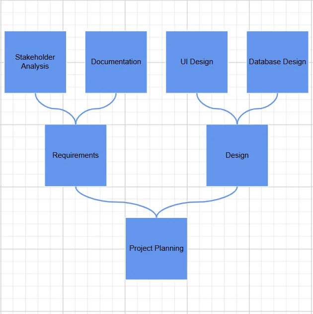
The Orientation property controls the direction in which the mind map expands. By default, the layout is set to Horizontal, which means nodes are arranged from left to right. To change the layout to vertical, set the Orientation property to Vertical.
The following example demonstrates configuring the mind map layout with a vertical orientation during component initialization.
@using Syncfusion.Blazor.Diagram

<SfDiagramComponent @ref="_diagram" Height="600px" NodeCreating="OnNodeCreating" ConnectorCreating="OnConnectorCreating">
    <RulerSettings>
        <HorizontalRuler></HorizontalRuler>
        <VerticalRuler></VerticalRuler>
    </RulerSettings>
    <DataSourceSettings ID="Id" ParentID="ParentId" DataSource="@DataSource">
    </DataSourceSettings>
    <Layout Type="LayoutType.MindMap" @bind-Orientation="SelectedOrientation" GetBranch="GetBranch" HorizontalSpacing="50">
        <LayoutMargin Top="20" Left="20"></LayoutMargin>
    </Layout>
</SfDiagramComponent>

@code {
    private SfDiagramComponent? _diagram;
    public LayoutOrientation SelectedOrientation { get; set; } = LayoutOrientation.Vertical;
    public List<OrientationItem> LayoutOrientationOptions { get; set; } = new()
    {
        new OrientationItem { Text = "Vertical", Value = LayoutOrientation.Vertical },
        new OrientationItem { Text = "Horizontal", Value = LayoutOrientation.Horizontal },
        new OrientationItem { Text = "Left to Right", Value = LayoutOrientation.LeftToRight },
        new OrientationItem { Text = "Right to Left", Value = LayoutOrientation.RightToLeft }
    };

    public List<MindMapDetails> DataSource { get; set; } = new()
    {
        new MindMapDetails { Id = "1", Label = "Project Planning", ParentId = "", Branch = "Root" },
        new MindMapDetails { Id = "2", Label = "Requirements", ParentId = "1", Branch = "Right" },
        new MindMapDetails { Id = "3", Label = "Design", ParentId = "1", Branch = "Right" },
        new MindMapDetails { Id = "5", Label = "Stakeholder Analysis", ParentId = "2", Branch = "SubRight" },
        new MindMapDetails { Id = "6", Label = "Documentation", ParentId = "2", Branch = "SubRight" },
        new MindMapDetails { Id = "7", Label = "UI Design", ParentId = "3", Branch = "SubRight" },
        new MindMapDetails { Id = "8", Label = "Database Design", ParentId = "3", Branch = "SubRight" }
    };

    private BranchType GetBranch(IDiagramObject obj)
    {
        if (obj is not Node node)
            return BranchType.Left;
        if (node.Data is not MindMapDetails mindMapData || string.IsNullOrWhiteSpace(mindMapData.Branch))
            return BranchType.Left;
        return Enum.TryParse(mindMapData.Branch, out BranchType branchType)
            ? branchType
            : BranchType.SubLeft;
    }

    // Method triggered by button click at runtime to set diagram orientation to vertical.
    private void ChangeLayoutOrientation()
    {
       _diagram!.Layout.Orientation = LayoutOrientation.Vertical;
    }

    private void OnNodeCreating(IDiagramObject obj)
    {
        if (obj is not Node node)
            return;
        // Apply default node styling.
        node.Height = 100;
        node.Width = 100;
        node.BackgroundColor = "#6BA5D7";
        node.Style = new ShapeStyle
        {
            Fill = "#6495ED",
            StrokeWidth = 1,
            StrokeColor = "white"
        };
        node.Shape = new BasicShape { Type = NodeShapes.Basic };
        // Add annotation with label from data.
        if (node.Data is MindMapDetails mindMapData && !string.IsNullOrWhiteSpace(mindMapData.Label))
        {
            node.Annotations = new DiagramObjectCollection<ShapeAnnotation>
            {
                new ShapeAnnotation { Content = mindMapData.Label }
            };
        }
    }

    private void OnConnectorCreating(IDiagramObject obj)
    {
        if (obj is not Connector connector)
            return;
        connector.Type = ConnectorSegmentType.Bezier;
        connector.Style = new ShapeStyle
        {
            StrokeColor = "#6495ED",
            StrokeWidth = 2
        };
        connector.TargetDecorator = new DecoratorSettings
        {
            Shape = DecoratorShape.None
        };
    }

    public class OrientationItem
    {
        public string Text { get; set; } = string.Empty;
        public LayoutOrientation Value { get; set; }
    }

    public class MindMapDetails
    {
        public string Id { get; set; } = string.Empty;
        public string Label { get; set; } = string.Empty;
        public string ParentId { get; set; } = string.Empty;
        public string Branch { get; set; } = string.Empty;
        public string Fill { get; set; } = string.Empty;
    }
}
A complete working sample can be downloaded from GitHub.
The following example demonstrates how to update the layout orientation dynamically at runtime using both data binding and direct method calls.
@using Syncfusion.Blazor.Diagram
@using Syncfusion.Blazor.DropDowns

<div style="display:grid;gap:20px;">
    <SfDiagramComponent @ref="_diagram" Height="600px" NodeCreating="OnNodeCreating" ConnectorCreating="OnConnectorCreating">
        <RulerSettings>
            <HorizontalRuler></HorizontalRuler>
            <VerticalRuler></VerticalRuler>
        </RulerSettings>
        <DataSourceSettings ID="Id" ParentID="ParentId" DataSource="@DataSource">
        </DataSourceSettings>
        <Layout Type="LayoutType.MindMap" @bind-Orientation="SelectedOrientation" GetBranch="GetBranch"
                HorizontalSpacing="50">
            <LayoutMargin Top="20" Left="20"></LayoutMargin>
        </Layout>
    </SfDiagramComponent>
    <div style="display:flex;gap:20px;">
        <SfDropDownList TValue="LayoutOrientation" TItem="OrientationItem" DataSource="LayoutOrientationOptions"
                        @bind-Value="SelectedOrientation" Placeholder="Select Orientation" Width="300px">
            <DropDownListFieldSettings Text="Text" Value="Value"></DropDownListFieldSettings>
        </SfDropDownList>
        <SfButton Content="Set to Vertical" IsPrimary="true" IconCss="e-icons e-refresh" OnClick="ChangeLayoutOrientation">
        </SfButton>
    </div>
</div>

@code {
    private SfDiagramComponent? _diagram;

    // Property bound to dropdown and diagram layout, updated at runtime by user interaction.
    public LayoutOrientation SelectedOrientation { get; set; } = LayoutOrientation.Vertical;

    public List<OrientationItem> LayoutOrientationOptions { get; set; } = new()
    {
        new OrientationItem { Text = "Vertical", Value = LayoutOrientation.Vertical },
        new OrientationItem { Text = "Horizontal", Value = LayoutOrientation.Horizontal },
        new OrientationItem { Text = "Left to Right", Value = LayoutOrientation.LeftToRight },
        new OrientationItem { Text = "Right to Left", Value = LayoutOrientation.RightToLeft }
    };

    public List<MindMapDetails> DataSource { get; set; } = new()
    {
        new MindMapDetails { Id = "1", Label = "Project Planning", ParentId = "", Branch = "Root" },
        new MindMapDetails { Id = "2", Label = "Requirements", ParentId = "1", Branch = "Right" },
        new MindMapDetails { Id = "3", Label = "Design", ParentId = "1", Branch = "Right" },
        new MindMapDetails { Id = "5", Label = "Stakeholder Analysis", ParentId = "2", Branch = "SubRight" },
        new MindMapDetails { Id = "6", Label = "Documentation", ParentId = "2", Branch = "SubRight" },
        new MindMapDetails { Id = "7", Label = "UI Design", ParentId = "3", Branch = "SubRight" },
        new MindMapDetails { Id = "8", Label = "Database Design", ParentId = "3", Branch = "SubRight" }
    };

    private BranchType GetBranch(IDiagramObject obj)
    {
        if (obj is not Node node)
            return BranchType.Left;
        if (node.Data is not MindMapDetails mindMapData || string.IsNullOrWhiteSpace(mindMapData.Branch))
            return BranchType.Left;
        return Enum.TryParse(mindMapData.Branch, out BranchType branchType)
            ? branchType
            : BranchType.SubLeft;
    }

    // Method triggered by button click at runtime to set diagram orientation to vertical.
    private void ChangeLayoutOrientation()
    {
       _diagram.Layout.Orientation = LayoutOrientation.Vertical;
    }

    private void OnNodeCreating(IDiagramObject obj)
    {
        if (obj is not Node node)
            return;
        // Apply default node styling.
        node.Height = 100;
        node.Width = 100;
        node.BackgroundColor = "#6BA5D7";
        node.Style = new ShapeStyle
        {
            Fill = "#6495ED",
            StrokeWidth = 1,
            StrokeColor = "white"
        };
        node.Shape = new BasicShape { Type = NodeShapes.Basic };
        // Add annotation with label from data.
        if (node.Data is MindMapDetails mindMapData && !string.IsNullOrWhiteSpace(mindMapData.Label))
        {
            node.Annotations = new DiagramObjectCollection<ShapeAnnotation>
            {
                new ShapeAnnotation { Content = mindMapData.Label }
            };
        }
    }

    private void OnConnectorCreating(IDiagramObject obj)
    {
        if (obj is not Connector connector)
            return;
        connector.Type = ConnectorSegmentType.Bezier;
        connector.Style = new ShapeStyle
        {
            StrokeColor = "#6495ED",
            StrokeWidth = 2
        };
        connector.TargetDecorator = new DecoratorSettings
        {
            Shape = DecoratorShape.None
        };
    }

    public class OrientationItem
    {
        public string Text { get; set; } = string.Empty;
        public LayoutOrientation Value { get; set; }
    }

    public class MindMapDetails
    {
        public string Id { get; set; } = string.Empty;
        public string Label { get; set; } = string.Empty;
        public string ParentId { get; set; } = string.Empty;
        public string Branch { get; set; } = string.Empty;
        public string Fill { get; set; } = string.Empty;
    }
}A complete working sample can be downloaded from GitHub.
The following table outlines the various orientation types available:
| Orientation Type | Description |
|---|---|
Horizontal |
Aligns the tree layout from left to right |
Vertical |
Aligns the tree layout from top to bottom |