How can I help you?
Connector in Diagram Component
2 Feb 202624 minutes to read
Connectors create links between points, nodes or ports to represent the relationships between them.
How to Create and Customize Connectors
A Connector is created by defining source and target points of the connector. The path to be drawn can be defined with a collection of segments.
To learn how to create and customize connectors easily in the Blazor Diagram component, watch the following video:
How to Add Connectors Using the Connectors Collection
Use the SourcePoint and TargetPoint properties of connector to define the endpoints of a connector.
The following code example illustrates how to add a connector through the connectors collection.
@using Syncfusion.Blazor.Diagram

<SfDiagramComponent Width="1000px" Height="500px" Connectors="@_connectors ">
    <SnapSettings Constraints="@_snapConstraints "></SnapSettings>
</SfDiagramComponent>

@code
{
    private SnapConstraints _snapConstraints  = SnapConstraints.None;
    //Defines diagram's connector collection.
    private DiagramObjectCollection<Connector> _connectors  = new DiagramObjectCollection<Connector>();

    protected override void OnInitialized()
    {
        Connector connector = new Connector()
        {
            ID = "connector1",
            // Set the source and target point of the connector.
            SourcePoint = new DiagramPoint() { X = 100, Y = 100 },
            TargetPoint = new DiagramPoint() { X = 200, Y = 200 },
            // Type of the connector segments.
            Type = ConnectorSegmentType.Straight
        };
        _connectors .Add(connector);
    }
}
A complete working sample can be downloaded from GitHub.

Note:
- The ID of each connector should be unique so it is further used to find the connector at runtime and perform any customization.
- Connector ID should not start with numbers or special characters and should not contain special characters such as underscores(_) or spaces.
How to Add Connectors at Runtime
Add a connector at runtime by adding it to the connectors collection in the Diagram component. The following code explains how to add connectors at runtime.
@using Syncfusion.Blazor.Diagram
@using Syncfusion.Blazor.Buttons

<SfButton Content="Add Connector" OnClick="@AddConnector" />
<SfDiagramComponent Width="1000px" Height="500px" Connectors="@_connectors" />

@code
{
    //Defines diagram's connector collection.
    private DiagramObjectCollection<Connector> _connectors = new DiagramObjectCollection<Connector>();

    protected override void OnInitialized()
    {
        Connector connector = new Connector()
        {
            ID = "connector1",
            SourcePoint = new DiagramPoint() { X = 100, Y = 100 },
            TargetPoint = new DiagramPoint() { X = 200, Y = 200 },
            Type = ConnectorSegmentType.Straight
        };
        _connectors.Add(connector);
    }

    private void AddConnector()
    {
        Connector newConnector = new Connector()
        {
            ID = "connector2",
            SourcePoint = new DiagramPoint() { X = 300, Y = 300 },
            TargetPoint = new DiagramPoint() { X = 400, Y = 400 },
            Type = ConnectorSegmentType.Straight
        };
        //Add the connector at the runtime.
        _connectors.Add(newConnector);
    }
}A complete working sample can be downloaded from GitHub.
How to Clone a Connector at Runtime
Clone is a virtual method on connector that creates a copy of a diagram object. After cloning, set a unique ID for the cloned connector. The following code demonstrates how to clone the connector during runtime.
@using Syncfusion.Blazor.Diagram
@using System.Collections.ObjectModel
@using Syncfusion.Blazor.Buttons
@inject IJSRuntime js

<SfButton Content="Clone Connector" OnClick="@CloneConnectors" />
<SfDiagramComponent @ref="_diagram" Width="50%" Height="500px" @bind-Connectors="@_connectors"></SfDiagramComponent>

@functions
{
    private SfDiagramComponent _diagram;
    private DiagramObjectCollection<Connector> _connectors = new DiagramObjectCollection<Connector>();

    protected override void OnInitialized()
    {
        Connector connector1 = new Connector() { ID = "connector1", SourcePoint = new DiagramPoint() { X = 100, Y = 10 }, TargetPoint = new DiagramPoint() { X = 200, Y = 100 }, Type = ConnectorSegmentType.Straight };
        _connectors.Add(connector1);
    }

    private async Task CloneConnectors()
    {
        Connector connector = _connectors[0].Clone() as Connector;
        connector.ID = RandomId();
        connector.SourcePoint = new DiagramPoint { X = 100, Y = 100 };
        connector.TargetPoint = new DiagramPoint { X = 200, Y = 100 };
        await _diagram.AddDiagramElementsAsync(new DiagramObjectCollection<NodeBase>() { connector });
    }

    private string RandomId()
    {
        Random random = new Random();
        const string Chars = "ABCDEFGHIJKLMNOPQRSTUVWXTZabcdefghiklmnopqrstuvwxyz";
#pragma warning disable CA5394 // Do not use insecure randomness
        return new string(Enumerable.Repeat(Chars, 5)
          .Select(s => s[random.Next(s.Length)]).ToArray());
#pragma warning restore CA5394 // Do not use insecure randomness
    }
}
A complete working sample can be downloaded from GitHub
How to Add a Connector with Annotations at Runtime
Add a connector with annotations at runtime in the diagram component by using the AddDiagramElementsAsync method.
The following code explains how to add a connector with annotation at runtime by using the AddDiagramElementsAsync method.
@using Syncfusion.Blazor.Diagram
@using Syncfusion.Blazor.Buttons

<SfButton Content="Add Connector" OnClick="@AddConnector" />
<SfDiagramComponent @ref="_diagram" Width="1000px" Height="500px" Connectors="@_connectors"></SfDiagramComponent>

@code
{
    private SfDiagramComponent _diagram;

    //Defines diagram's connector collection.
    private DiagramObjectCollection<Connector> _connectors = new DiagramObjectCollection<Connector>();

    private DiagramObjectCollection<NodeBase> _connectorCollection = new DiagramObjectCollection<NodeBase>();

    protected override void OnInitialized()
    {
        Connector connector = new Connector()
        {
            ID = "connector1",
            SourcePoint = new DiagramPoint() { X = 100, Y = 100 },
            TargetPoint = new DiagramPoint() { X = 200, Y = 200 },
            Type = ConnectorSegmentType.Straight
        };
        _connectors.Add(connector);
    }

    private async void AddConnector()
    {
        Connector newConnector = new Connector()
        {
            ID = "connector2",
            SourcePoint = new DiagramPoint() { X = 300, Y = 300 },
            TargetPoint = new DiagramPoint() { X = 400, Y = 400 },
            Type = ConnectorSegmentType.Straight,
            Annotations = new DiagramObjectCollection<PathAnnotation>()
            {
                new PathAnnotation()
                {
                    Content="NewAnnotation"
                }
            },
        };
        _connectorCollection.Add(newConnector);
        await _diagram.AddDiagramElementsAsync(_connectorCollection);
    }
}How to Add a Connector to the Symbol Palette
Connectors can be predefined and added to the symbol palette. Then, drag and drop the connectors into the diagram when required.
@using Syncfusion.Blazor.Diagram
@using Syncfusion.Blazor.Diagram.SymbolPalette

<div style="width: 200px; float: left">
    <SfSymbolPaletteComponent Height="600px" @ref="@_paletteInstance" Palettes="@_palettes">
    </SfSymbolPaletteComponent>
</div>

<SfDiagramComponent @ref="@_diagramInstance" Width="1000px" Height="500px" Connectors="@_connectors" />

@code
{
    private SfSymbolPaletteComponent _paletteInstance;
    private SfDiagramComponent _diagramInstance;
    //Defines Symbol palette's PaletteConnector collection.
    private DiagramObjectCollection<NodeBase> _paletteConnector = new DiagramObjectCollection<NodeBase>();
    private DiagramObjectCollection<Palette> _palettes = new DiagramObjectCollection<Palette>();
    private DiagramObjectCollection<Connector> _connectors = new DiagramObjectCollection<Connector>();

    protected override async Task OnAfterRenderAsync(bool firstRender)
    {
        _paletteInstance.Targets = new DiagramObjectCollection<SfDiagramComponent>() { };
        _paletteInstance.Targets.Add(_diagramInstance);
    }

    protected override void OnInitialized()
    {
        Connector connector = new Connector()
        {
            ID = "connector1",
            // Set the source and target point of the connector.
            SourcePoint = new DiagramPoint() { X = 100, Y = 100 },
            TargetPoint = new DiagramPoint() { X = 200, Y = 200 },
            // Type of the connector segments.
            Type = ConnectorSegmentType.Straight
        };
        _connectors.Add(connector);

        _paletteConnector = new DiagramObjectCollection<NodeBase>();
        Connector connector1 = new Connector
        {
            ID = "Link1",
            Type = ConnectorSegmentType.Straight,
            SourcePoint = new DiagramPoint() { X = 0, Y = 0 },
            TargetPoint = new DiagramPoint() { X = 60, Y = 60 }
        };
        _paletteConnector.Add(connector1 as NodeBase);

        Connector connector2 = new Connector
        {
            ID = "Link2",
            Type = ConnectorSegmentType.Orthogonal,
            SourcePoint = new DiagramPoint() { X = 0, Y = 0 },
            TargetPoint = new DiagramPoint() { X = 60, Y = 60 },
            TargetDecorator = new DecoratorSettings() { Shape = DecoratorShape.OpenArrow },
            Style = new ShapeStyle() { StrokeWidth = 1 }
        };
        _paletteConnector.Add(connector2 as NodeBase);

        Connector connector3 = new Connector
        {
            ID = "Link3",
            Type = ConnectorSegmentType.Bezier,
            SourcePoint = new DiagramPoint() { X = 0, Y = 0 },
            TargetPoint = new DiagramPoint() { X = 60, Y = 60 },
            TargetDecorator = new DecoratorSettings() { Shape = DecoratorShape.None },
        };
        _paletteConnector.Add(connector3 as NodeBase);

        _palettes = new DiagramObjectCollection<Palette>()
        {
            new Palette(){ Symbols = _paletteConnector , Title = "Connectors", IsExpanded = true },
        };
    }
}
A complete working sample can be downloaded from GitHub

How to Draw Connectors Using the Drawing Object
Connectors can be interactively drawn by clicking and dragging on the diagram surface by using the DrawingObject.

How to Remove Connectors at Runtime
Remove a connector from the diagram at runtime by using the Remove method.
The following code shows how to remove a connector at runtime.
@using Syncfusion.Blazor.Diagram
@using Syncfusion.Blazor.Buttons

<SfButton Content="Remove Connector" OnClick="@RemoveConnector" />
<SfDiagramComponent Width="1000px" Height="500px" Connectors="@_connectors">
    <SnapSettings Constraints="@_snapConstraints"></SnapSettings>
</SfDiagramComponent>

@code
{
    //Defines snap consttraints
    private SnapConstraints _snapConstraints = SnapConstraints.None;
    //Defines diagram's connector collection
    private DiagramObjectCollection<Connector> _connectors = new DiagramObjectCollection<Connector>();

    protected override void OnInitialized()
    {
        Connector connector = new Connector()
        {
            ID = "connector1",
            // Set the source and target point of the connector
            SourcePoint = new DiagramPoint() { X = 100, Y = 100 },
            TargetPoint = new DiagramPoint() { X = 200, Y = 200 },
            TargetDecorator = new DecoratorSettings()
            {
                Shape = DecoratorShape.Arrow,
                // Style of the connector segment
                Style = new ShapeStyle() { Fill = "#6f409f", StrokeColor = "#6f409f", StrokeWidth = 1 }
            },
            Style = new ShapeStyle() { StrokeColor = "#6f409f", StrokeWidth = 1 },
            // Type of the connector
            Type = ConnectorSegmentType.Straight,
        };
        _connectors.Add(connector);
    }

    private void RemoveConnector()
    {
        // Remove connector at runtime
        _connectors.Remove(_connectors[0]);
    }
}A complete working sample can be downloaded from GitHub
A connector can also be removed from the diagram by using the native RemoveAt method. Refer to the following example that shows how to remove the connector at runtime.
public void RemoveConnector()
{
    connectors.RemoveAt(0);
}
How to Update Connector Properties at Runtime
Connector properties can be changed at runtime.
The following code example explains how to change the connector properties.
@using Syncfusion.Blazor.Diagram
@using Syncfusion.Blazor.Buttons

<SfButton Content="Update Connector" OnClick="@UpdateConnector" />
<SfDiagramComponent @ref="_diagram" Width="1000px" Height="500px" Connectors="@_connectors">
    <SnapSettings Constraints="@_snapConstraints"></SnapSettings>
</SfDiagramComponent>

@code {
    //Reference the diagram
    private SfDiagramComponent _diagram;
    //Defines the snap constraints
    private SnapConstraints _snapConstraints = SnapConstraints.None;
    //Defines diagram's connector collection
    private DiagramObjectCollection<Connector> _connectors = new DiagramObjectCollection<Connector>();

    protected override void OnInitialized()
    {
        Connector connector = new Connector()
        {
            ID = "connector1",
            SourcePoint = new DiagramPoint() { X = 100, Y = 100 },
            TargetPoint = new DiagramPoint() { X = 200, Y = 200 },
            TargetDecorator = new DecoratorSettings()
            {
                Shape = DecoratorShape.Arrow,
                Style = new ShapeStyle()
                {
                    Fill = "#6f409f",
                    StrokeColor = "#6f409f",
                    StrokeWidth = 1
                }
            },
            Style = new ShapeStyle() { StrokeColor = "#6f409f", StrokeWidth = 1 },
            // Type of the connector
            Type = ConnectorSegmentType.Straight,
        };
        _connectors.Add(connector);
    }

    //Method to update connector at runtime.
    private async Task UpdateConnector()
    {
        _diagram.BeginUpdate();
        _diagram.Connectors[0].SourcePoint.X = 50;
        _diagram.Connectors[0].SourcePoint.Y = 50;
        await _diagram.EndUpdateAsync();
    }
}A complete working sample can be downloaded from GitHub.
NOTE
BeginUpdate and EndUpdateAsync methods allow you to temporarily stop the continuous update of the control and resume it once the updates are complete.
Connections
Connectors are used to create links between two points, nodes or ports to represent relationships between them.
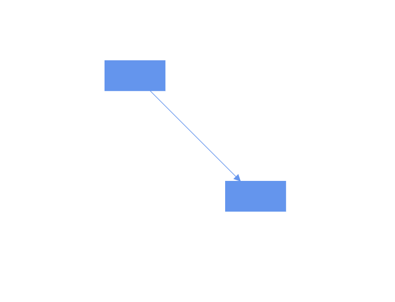
How to Connect Nodes Using Source and Target ID
Use the SourceID and TargetID properties to define the nodes to be connected.
The following code example illustrates how to connect two nodes.
@using Syncfusion.Blazor.Diagram

<SfDiagramComponent @ref="_diagram" Width="1000px" Height="500px" Nodes="@_nodes" Connectors="@_connectors" />

@code
{
    private SfDiagramComponent _diagram;
    private DiagramObjectCollection<Connector> _connectors = new DiagramObjectCollection<Connector>();
    private DiagramObjectCollection<Node> _nodes = new DiagramObjectCollection<Node>();

    protected override void OnInitialized()
    {
        _nodes = new DiagramObjectCollection<Node>()
        {
            new Node()
            {
                OffsetX = 100,
                OffsetY = 100,
                Height = 50,
                Width = 100,
                ID = "node1",
                Style = new ShapeStyle(){ Fill = "#6495ED", StrokeColor = "#6495ED" },
                Shape = new BasicShape() { Type = NodeShapes.Basic, Shape = NodeBasicShapes.Rectangle }
            },
            new Node()
            {
                OffsetX = 300,
                OffsetY = 300,
                Height = 50,
                Width = 100,
                ID = "node2",
                Style = new ShapeStyle(){ Fill = "#6495ED", StrokeColor = "#6495ED" },
                Shape = new BasicShape() { Type = NodeShapes.Basic, Shape = NodeBasicShapes.Rectangle }
            }
        };
        Connector connector = new Connector()
        {
            ID = "connector1",
            //Source node id of the connector.
            SourceID = "node1",
            TargetDecorator = new DecoratorSettings()
            {
                Style = new ShapeStyle()
                {
                    Fill = "#6495ED",
                    StrokeColor = "#6495ED",
                }
            },
            //Target node id of the connector.
            TargetID = "node2",
            Style = new ShapeStyle()
            {
                Fill = "#6495ED",
                StrokeColor = "#6495ED",
            },
            // Type of the connector.
            Type = ConnectorSegmentType.Straight,
        };
        _connectors.Add(connector);
    }
}
A complete working sample can be downloaded from GitHub.
-
Removing NodeConstraints.InConnect from Default, the node accepts only an outgoing connection to dock in it. Similarly, when you remove NodeConstraints.OutConnect from Default, the node accepts only an incoming connection to dock in it.
-
Removing both
InConnectandOutConnectconstraints fromDefault, the node restricts connectors from establishing a connection to it.
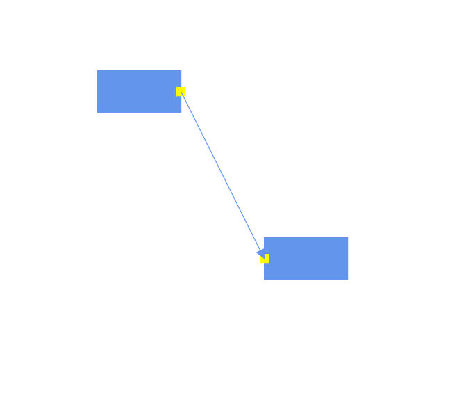
How to Connect Nodes Using Specific Ports
Use the SourcePortID and TargetPortID properties to create connections between specific points on the source or target nodes.
The following code example illustrates how to create port to port connections.
@using Syncfusion.Blazor.Diagram

<SfDiagramComponent @ref="_diagram" Width="1000px" Height="500px" Nodes="@_nodes" Connectors="@_connectors" />

@code
{
    private SfDiagramComponent _diagram;
    private DiagramObjectCollection<Connector> _connectors = new DiagramObjectCollection<Connector>();
    private DiagramObjectCollection<Node> _nodes = new DiagramObjectCollection<Node>();

    protected override void OnInitialized()
    {
        _nodes = new DiagramObjectCollection<Node>()
        {
            new Node()
            {
                OffsetX = 100,
                OffsetY = 100,
                Height = 50,
                Ports = new DiagramObjectCollection<PointPort>()
                {
                    new PointPort()
                    {
                        ID="port1",
                        Visibility = PortVisibility.Visible,
                        Offset = new DiagramPoint() { X = 1, Y = 0.5},
                        Height = 10, Width = 10,
                        Style =  new ShapeStyle(){Fill = "yellow", StrokeColor = "yellow"}
                    }
                },
                Width = 100,
                ID = "node1",
                Style = new ShapeStyle(){ Fill = "#6495ED", StrokeColor = "#6495ED"},
                Shape = new BasicShape() { Type = NodeShapes.Basic, Shape = NodeBasicShapes.Rectangle }
            },
            new Node()
            {
                OffsetX = 300,
                OffsetY = 300,
                Height = 50,
                Width = 100,
                ID = "node2",
                Ports = new DiagramObjectCollection<PointPort>()
                {
                    new PointPort()
                    {
                        ID="port2",
                        Visibility = PortVisibility.Visible,
                        Offset = new DiagramPoint() { X = 0, Y = 0.5},
                        Height = 10, Width = 10,
                        Style =  new ShapeStyle(){Fill = "yellow", StrokeColor = "yellow"}
                    }
                },
                Style = new ShapeStyle(){ Fill = "#6495ED", StrokeColor = "#6495ED" },
                Shape = new BasicShape() { Type = NodeShapes.Basic, Shape = NodeBasicShapes.Rectangle }
            }
        };
        Connector connector = new Connector()
        {
            ID = "connector1",
            //Source node id of the connector.
            SourceID = "node1",
            //source node port id.
            SourcePortID = "port1",
            //Target node id of the connector.
            TargetID = "node2",
            //Target node port id.
            TargetPortID = "port2",
            TargetDecorator = new DecoratorSettings()
            {
                Style = new ShapeStyle()
                {
                    Fill = "#6495ED",
                    StrokeColor = "#6495ED",
                }
            },
            Style = new ShapeStyle()
            {
                Fill = "#6495ED",
                StrokeColor = "#6495ED",
            },
            // Type of the connector.
            Type = ConnectorSegmentType.Straight,
        };
        _connectors.Add(connector);
    }
}
A complete working sample can be downloaded from GitHub.
- Set PortConstraints to InConnect, to accept only incoming connection to dock in it. Similarly, Set PortConstraints to OutConnect, to accept only an outgoing connection to dock in it.
- Setting None, the port restricts connectors from establishing a connection to the port.
See also
-
How to Customize Connector Styles in a Hierarchical Layout in Blazor Diagram
-
Why save and load functionality for nodes and connectors in Blazor Diagram?
-
How to Add Nodes or Connectors by Clicking on the Diagram in Syncfusion® Blazor Diagram Component?
-
How to add nodes and connectors at runtime asynchronously in Blazor Diagram Component?
-
How to Select and Highlight Ports and Connect Selected Elements in Syncfusion® Blazor Diagram