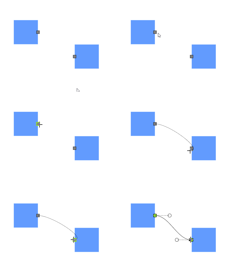
Port Interaction in Diagram Component
2 Feb 202612 minutes to read
Ports can be used to start connector drawing by enabling the Draw flag in PortConstraints for the desired port.
How to Draw Connector from Node Port
Draw connectors from a node port by enabling the Draw constraint on the port’s Constraints property. By default, the connector segment type is Orthogonal.
The following code explains how to draw a connector by using port constraints.
@using Syncfusion.Blazor.Diagram

<SfDiagramComponent Height="600px" Nodes="@_nodes" />

@code
{
    private DiagramObjectCollection<Node> _nodes;

    protected override void OnInitialized()
    {
        _nodes = new DiagramObjectCollection<Node>();
        // A node is created and stored in the nodes array.
        Node node = new Node()
        {
            // Position of the node.
            OffsetX = 250,
            OffsetY = 250,
            // Size of the node.
            Width = 100,
            Height = 100,
            Style = new ShapeStyle() { Fill = "#6495ED", StrokeColor = "white" },
            // Initialize port collection.
            Ports = new DiagramObjectCollection<PointPort>()
            {
                new PointPort()
                {
                    ID = "port1",
                    Offset = new DiagramPoint() { X = 1, Y = 0.5 },
                    Visibility = PortVisibility.Visible,
                    //Set the style for the port.
                    Style = new ShapeStyle()
                    {
                        Fill = "gray",
                        StrokeColor = "black"
                     },
                    Width = 12,
                    Height = 12,
                    // Sets the shape of the port as Square.
                    Shape = PortShapes.Square,
                    // Enable draw operation for Port.
                    Constraints = PortConstraints.Default | PortConstraints.Draw
                }
            },
        };
        _nodes.Add(node);
    }
}
A complete working sample can be downloaded from GitHub

How to Draw Connector from Connector Port
Draw connectors from a connector port by enabling the Draw constraint on the port’s Constraints property. By default, the connector segment type is Orthogonal.
The following code explains how to draw a connector by using port constraints.
@using Syncfusion.Blazor.Diagram

<SfDiagramComponent Height="600px" Connectors="@_connectors">
</SfDiagramComponent>

@code
{
    //Define diagram's connector collection
    private DiagramObjectCollection<Connector> _connectors;

    protected override void OnInitialized()
    {
        // A connector is created and stored in connectors collection.
        _connectors = new DiagramObjectCollection<Connector>();

        // Create an orthogonal connector
        Connector connector = new Connector()
        {
            ID = "connector",
            SourcePoint = new DiagramPoint() { X = 400, Y = 200 },
            TargetPoint = new DiagramPoint() { X = 550, Y = 350 },
            Type = ConnectorSegmentType.Bezier,
            Ports = new DiagramObjectCollection<ConnectorPort>()
            {
                new ConnectorPort()
                {
                    ID = "port",
                    Visibility = PortVisibility.Visible,
                    Shape = PortShapes.Square,
                    Constraints = PortConstraints.Default | PortConstraints.Draw
                }
            }
        };
        _connectors.Add(connector);
    }
}
A complete working sample can be downloaded from GitHub

How to Draw Different Connector Types from Port
Change the default connector type while drawing the connector from the port by setting the specific connector type instance to the DrawingObject property. This enables the drawing of various connector types from the port, including:
- Straight
- Bezier
- Polyline
- Orthogonal
- Free Hand
The following code explains how to draw the connector by using port constraints.
@using Syncfusion.Blazor.Diagram

<SfDiagramComponent @ref="_diagram" Height="600px" Nodes="@_nodes" DrawingObject="@_drawingObject"/>

@code
{
    private DiagramObjectCollection<Node> _nodes;
    private SfDiagramComponent _diagram;
    private IDiagramObject _drawingObject;
    protected override void OnInitialized()
    {
        _nodes = new DiagramObjectCollection<Node>();
        // Nodes are created and stored in the nodes array.
        Node node1 = new Node()
        {
            // Position of the node.
            OffsetX = 250,
            OffsetY = 250,
            // Size of the node.
            Width = 100,
            Height = 100,
            Style = new ShapeStyle() { Fill = "#6495ED", StrokeColor = "white" },
            // Initialize port collection.
            Ports = new DiagramObjectCollection<PointPort>()
            {
                new PointPort()
                {
                    ID = "port1",
                    Offset = new DiagramPoint() { X = 1, Y = 0.5 },
                    Visibility = PortVisibility.Visible,
                    //Set the style for the port.
                    Style= new ShapeStyle(){ Fill = "gray", StrokeColor = "black"},
                    // Sets the shape of the port as Square.
                    Width = 12, Height = 12, Shape = PortShapes.Square,
                    // Enable drag operation for Port.
                    Constraints = PortConstraints.Default|PortConstraints.Draw
                }
            },
        };
        _nodes.Add(node1);
        Node node2 = new Node()
        {
            // Position of the node.
            OffsetX = 500,
            OffsetY = 350,
            // Size of the node.
            Width = 100,
            Height = 100,
            Style = new ShapeStyle() { Fill = "#6495ED", StrokeColor = "white" },
            // Initialize port collection.
            Ports = new DiagramObjectCollection<PointPort>()
            {
                new PointPort()
                {
                    ID = "port1",
                    Offset = new DiagramPoint() { X = 0, Y = 0.5 },
                    Visibility = PortVisibility.Visible,
                    //Set the style for the port.
                    Style= new ShapeStyle(){ Fill = "gray", StrokeColor = "black"},
                    // Sets the shape of the port as Square.
                    Width = 12, Height = 12, Shape = PortShapes.Square,
                    // Enable drag operation for Port.
                    Constraints = PortConstraints.Default|PortConstraints.Draw
                }
            },
        };
        _nodes.Add(node2);
        _drawingObject = new Connector()
        {
            ID = "connector1",
            Type = ConnectorSegmentType.Bezier,
        };
    }
}
A complete working sample can be downloaded from GitHub.
