Positioning a Port in Diagram Component
3 Jul 202616 minutes to read
Customize the position and appearance of the port efficiently. Ports can be aligned relative to node boundaries. It has Margin, Offset, Horizontal, and Vertical alignment settings. It is quite tricky when all four alignments are used together but gives more control over alignments properties of the PointPort class. Ports of a node can be positioned using the following properties of PointPort.
- Offset
- HorizontalAlignment
- VerticalAlignment
- Margin
How to Change Offset at Runtime
Use Offset to place a port using fractional values relative to the node: 0 represents the top/left, 1 represents the bottom/right, and 0.5 represents the center along each axis.
@using Syncfusion.Blazor.Diagram

<SfDiagramComponent Height="600px" Nodes="@_nodes"/>

@code
{
    private DiagramObjectCollection<Node> _nodes;
    protected override void OnInitialized()
    {
        _nodes = new DiagramObjectCollection<Node>();
        // A node is created and stored in _nodes collection.
        Node node = new Node()
        {
            // Position of the node.
            OffsetX = 250,
            OffsetY = 250,
            // Size of the node.
            Width = 100,
            Height = 100,
            Style = new ShapeStyle() { Fill = "#6495ED", StrokeColor = "white" },
            // Initialize port collection.
            Ports = new DiagramObjectCollection<PointPort>()
            {
                new PointPort()
                {
                    ID = "port1",
                    // Sets the offset for the port.
                    Offset = new DiagramPoint() { X = 0, Y = 0.5 },
                    Visibility = PortVisibility.Visible,
                    //Set the style for the port.
                    Style= new ShapeStyle() { Fill = "gray", StrokeColor = "black" },
                    Width = 12,
                    Height = 12,
                    // Sets the shape of the port as Square .
                    Shape = PortShapes.Square
                }
            }
        };
        _nodes.Add(node);
    }
}
A complete working sample can be downloaded from GitHub
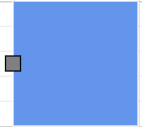
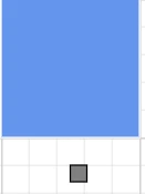
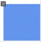
The following table shows the relationship between the shape port position and path port offset (fraction values).
| Offset values | Output |
|---|---|
| (0,0) | 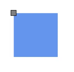 |
| (0,0.5) | 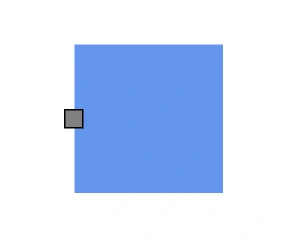 |
| (0,1) | 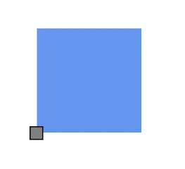 |
| (0.5,0) | 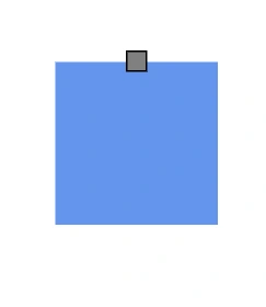 |
| (0.5,0.5) | 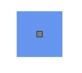 |
| (0.5,1) | 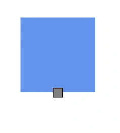 |
| (1,0) | 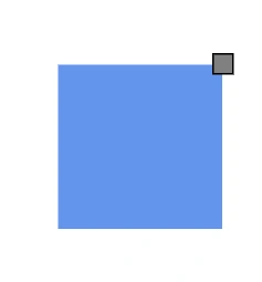 |
| (1,0.5) | 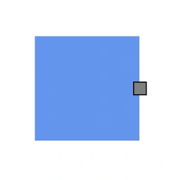 |
| (1,1) | 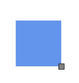 |
How to Set Path Position for Connector Port
Use the PathPosition property to place a connector port along the connector path. It accepts values between 0 to 1, where:
- 0 represents the start point of the connector
- 1 represents the end point of the connector
Note: The default value is 0.5, which places the port at the midpoint of the connector.
| PathPosition value | Output |
|---|---|
| 0 | 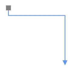 |
| 0.5 | 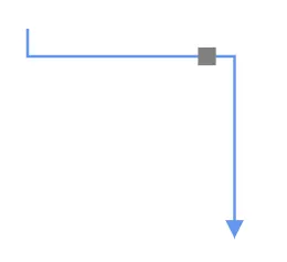 |
| 1 | 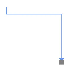 |
The following code example demonstrates how to set path position for a connector port.
@using Syncfusion.Blazor.Diagram

<SfDiagramComponent Height="600px" Connectors="@_connectors">
</SfDiagramComponent>

@code
{
    //Define diagram's connector collection
    private DiagramObjectCollection<Connector> _connectors;

    protected override void OnInitialized()
    {
        // A connector is created and stored in connectors collection.
        _connectors = new DiagramObjectCollection<Connector>();

        // Create connector
        Connector connector = new Connector()
        {
            ID = "connector",
            SourcePoint = new DiagramPoint() { X = 400, Y = 200 },
            TargetPoint = new DiagramPoint() { X = 550, Y = 350 },
            Type = ConnectorSegmentType.Orthogonal,
            Ports = new DiagramObjectCollection<ConnectorPort>()
            {
                new ConnectorPort()
                {
                    ID = "port",
                    Visibility = PortVisibility.Visible,
                    Shape = PortShapes.Square,
                    PathPosition = 0,
                }
            }
        };
        _connectors.Add(connector);
    }
}A complete working sample can be downloaded from GitHub
How to Change Horizontal and Vertical Alignment
HorizontalAlignment property of the port is used to set how the port is horizontally aligned at the port position determined from the fraction values, and VerticalAlignment property is used to set how the port is vertically aligned at the port position.
The following table shows all the possible alignments visually with offset (0, 0).
| Horizontal Alignment | Vertical Alignment | Output with Offset(0,0) |
|---|---|---|
| Left | Top | 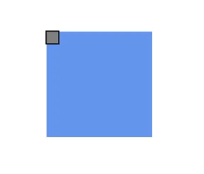 |
| Center | Top | 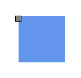 |
| Right | Top | 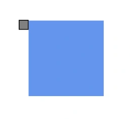 |
| Left | Center | 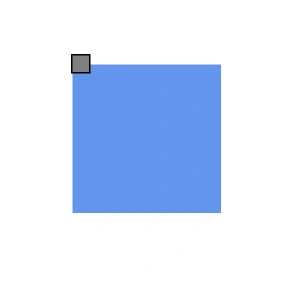 |
| Center | Center | 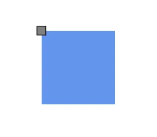 |
| Right | Center | 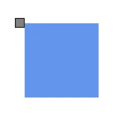 |
| Left | Bottom | 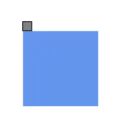 |
| Center | Bottom | 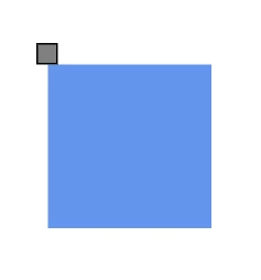 |
| Right | Bottom | 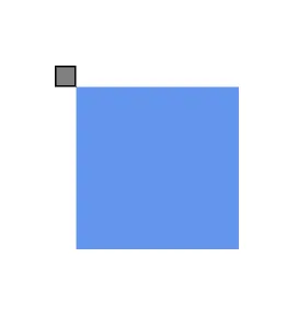 |
The following code shows how to align ports.
@using Syncfusion.Blazor.Diagram

<SfDiagramComponent Height="600px" Nodes="@_nodes"/>

@code
{
    private DiagramObjectCollection<Node> _nodes;
    protected override void OnInitialized()
    {
        _nodes = new DiagramObjectCollection<Node>();
        // A node is created and stored in _nodes array.
        Node node = new Node()
        {
            // Position of the node.
            OffsetX = 250,
            OffsetY = 250,
            // Size of the node.
            Width = 100,
            Height = 100,
            Style = new ShapeStyle() { Fill = "#6495ED", StrokeColor = "white" },
            // Initialize port collection.
            Ports = new DiagramObjectCollection<PointPort>()
            {
                new PointPort()
                {
                    ID = "port1",
                    Offset = new DiagramPoint() { X = 0, Y = 0 },
                    Visibility = PortVisibility.Visible,
                    //Set the style for the port.
                    Style = new ShapeStyle(){ Fill="gray", StrokeColor="black"},
                    Width = 12,
                    Height = 12,
                    // Sets the shape of the port as Square.
                    Shape = PortShapes.Square,
                    HorizontalAlignment = HorizontalAlignment.Center,
                    VerticalAlignment = VerticalAlignment.Center
                }
            }
        };
        _nodes.Add(node);
    }
}
A complete working sample can be downloaded from GitHub
NOTE
The default values for
HorizontalAlignmentandVerticalAlignmentareCenter. Alignment is positioned based on the offset value.
How to Update Margin for Port
Margin is an absolute value that adds some blank space to any one of its four sides. The ports can be displaced with the Margin property. The following code example explains how to align a port based on its Offset, HorizontalAlignment, VerticalAlignment, and Margin values.
@using Syncfusion.Blazor.Diagram

<SfDiagramComponent Height="600px" Nodes="@_nodes"/>

@code
{
    private DiagramObjectCollection<Node> _nodes;
    protected override void OnInitialized()
    {
        _nodes = new DiagramObjectCollection<Node>();
        // A node is created and stored in _nodes array.
        Node node = new Node()
        {
            // Position of the node.
            OffsetX = 250,
            OffsetY = 250,
            // Size of the node.
            Width = 100,
            Height = 100,
            Style = new ShapeStyle() { Fill = "#6495ED", StrokeColor = "white" },
            // Initialize port collection.
            Ports = new DiagramObjectCollection<PointPort>()
            {
                new PointPort()
                {
                    ID = "port1",
                    Offset = new DiagramPoint() { X = 0.5, Y = 1 },
                    Visibility = PortVisibility.Visible,
                    //Set the style for the port.
                    Style= new ShapeStyle() { Fill = "gray", StrokeColor = "black" },
                    Width = 12,
                    Height = 12,
                    // Sets the shape of the port as Square.
                    Shape = PortShapes.Square,
                    HorizontalAlignment = HorizontalAlignment.Left,
                    VerticalAlignment = VerticalAlignment.Top,
                    Margin = new DiagramThickness() { Top = 20 }
                }
            }
        };
        _nodes.Add(node);
    }
}
A complete working sample can be downloaded from GitHub