How can I help you?
Port Appearance in Diagram Component
2 Feb 202612 minutes to read
How to Customize Port Appearance
-
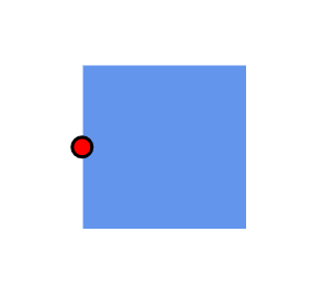
Change the port shape by using the Shape property. For available shapes, refer to Port Shapes. If you need to render a custom shape, then you can set shape to path and define path using the path data property.
-
Customize port style using the StrokeColor, StrokeWidth, and Fill properties.
-
Customize the port size using the Width and Height properties of port.
-
Control when a port is visible using the Visibility property.
The following code shows how to change the appearance of the port.
@using Syncfusion.Blazor.Diagram

<SfDiagramComponent Height="600px" Nodes="@_nodes" />

@code
{
    private DiagramObjectCollection<Node> _nodes;

    protected override void OnInitialized()
    {
        _nodes = new DiagramObjectCollection<Node>();
        // A node is created and stored in nodes array.
        Node node = new Node()
        {
            // Position of the node.
            OffsetX = 250,
            OffsetY = 250,
            // Size of the node.
            Width = 100,
            Height = 100,
            Style = new ShapeStyle() { Fill = "#6495ED", StrokeColor = "white" },
            // Initialize port collection
            Ports = new DiagramObjectCollection<PointPort>()
            {
                new PointPort()
                {
                    ID = "port1",
                    Offset = new DiagramPoint() { X = 0, Y = 0.5 },
                    Visibility = PortVisibility.Visible,
                    //Set the style for the port.
                    Style = new ShapeStyle()
                    {
                        Fill = "red",
                        StrokeColor = "black",
                        StrokeWidth = 2
                    },
                    Width = 12,
                    Height = 12,
                    // Sets the shape of the port as Circle .
                    Shape = PortShapes.Circle
                }
            },
        };
        _nodes.Add(node);
    }
}
A complete working sample can be downloaded from GitHub
How to Control the Port Visibility
The Visibility of ports depends upon the properties of Connect, Hidden, Hover, and Visible. By default, PortVisibility is set to Hidden.
| Property | Definition |
|---|---|
| Hover | Port is visible when the mouse hovers over the diagram element. |
| Hidden | Port is not visible for the diagram element. |
| Connect | Specifies to visible the port when mouse hovers the diagram element and enable the port constraints as InConnect and OutConnect. |
| Visible | Port is always visible for the DiagramElement. |
How to Use Different Port Shapes
We have provided some basic built-in PortShapes for the port. Find the shapes as follows.
- Circle
- Custom
- Square
- X
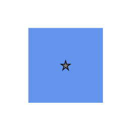
How to Customize Port Shape
Custom shapes are supported for ports. Provide custom path data instead of build-in shapes. The code example that explains how to change the custom shape for port.
@using Syncfusion.Blazor.Diagram

<SfDiagramComponent Height="600px" Nodes="@_nodes" />

@code
{
    private DiagramObjectCollection<Node> _nodes;

    protected override void OnInitialized()
    {
        _nodes = new DiagramObjectCollection<Node>();
        // A node is created and stored in nodes array.
        Node node = new Node()
        {
            // Position of the node
            OffsetX = 250,
            OffsetY = 250,
            // Size of the node.
            Width = 100,
            Height = 100,
            Style = new ShapeStyle() { Fill = "#6495ED", StrokeColor = "white" },
            // Initialize port collection.
            Ports = new DiagramObjectCollection<PointPort>()
            {
                new PointPort()
                {
                    ID = "port1",
                    Offset = new DiagramPoint() { X = 0.5, Y = 0.5 },
                    Visibility = PortVisibility.Visible,
                    //Set the style for the port.
                    Style = new ShapeStyle() { Fill = "gray", StrokeColor = "black" },
                    Width = 12,
                    Height = 12,
                    // Sets the shape of the port as Custom .
                    Shape = PortShapes.Custom,
                    // Sets the PathData for port.
                    PathData = "M540.3643,137.9336L546.7973,159.7016L570.3633,159.7296L550.7723,171.9366L558.9053,194.9966L540.3643,179.4996L521.8223,194.9966L529.9553,171.9366L510.3633,159.7296L533.9313,159.7016L540.3643,137.9336z"
                }
            },
        };
        _nodes.Add(node);
    }
}
A complete working sample can be downloaded from GitHub
How to Enable or Disable Port Behaviors Using Constraints
The constraints property allows enabling or disabling certain behaviors of ports. For more information about port constraints, refer to PortConstraints. Refer to Constraints for enabling or disabling port-related constraints.
The PortConstraints may have multiple behaviors like listed below:
| Constraints | Usage |
|---|---|
| None | Disables all port behaviors. |
| Draw | Enables or disables drawing a connector from the port. |
| InConnect | Enables or disables connecting incoming connectors to the port. |
| OutConnect | Enables or disables connecting outgoing connectors from the port. |
How to Add Additional Information for Port
The AdditionalInfo property allows you to maintain additional information for a port.
The following code shows how to set the AdditionalInfo value for a port.
@using Syncfusion.Blazor.Diagram
<SfDiagramComponent Height="600px" Nodes="@_nodes" />
@code
{
    private DiagramObjectCollection<Node> _nodes;
    protected override void OnInitialized()
    {
        _nodes = new DiagramObjectCollection<Node>();
        // Create a dictionary to hold additional information for the port.
        Dictionary<string, object> PortInfo = new Dictionary<string, object>();
        PortInfo.Add("portInfo", "Port A");
        // Create a port with additional info.
        PointPort port = new PointPort()
            {
                Offset = new DiagramPoint { X = 0.5, Y = 0.5 },
                Visibility=PortVisibility.Visible,
                AdditionalInfo = PortInfo
            };
        // A node is created and stored in nodes collection.
        Node node = new Node()
            {
                OffsetX = 250,
                OffsetY = 250,
                Width = 100,
                Height = 100,
                Style = new ShapeStyle()
                {
                    Fill = "#6BA5D7",
                    StrokeColor = "white"
                },
                Ports = new DiagramObjectCollection<PointPort>  { port }
            };
        // Add node.
        _nodes.Add(node);
    }
}A complete working sample can be downloaded from GitHub
Note: Like AdditionalInfo for Nodes, you can set any type of value for the AdditionalInfo property of a port.