Connector Interactions in Blazor Diagram Component
3 Jul 202624 minutes to read
Selection
DiagramSelectionSettings provides the visual representation of selected elements. It behaves like a container and allows to update the size, position, and rotation angle of the selected elements through interaction or programmatic changes. Single or multiple elements can be selected at a time.
How to Perform Single Selection
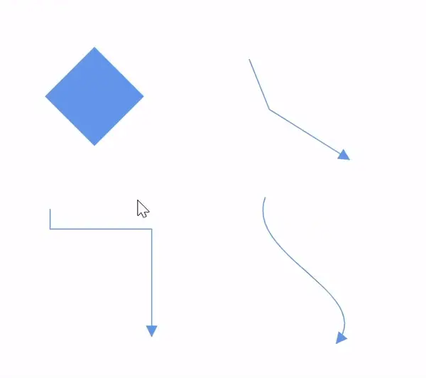
Select an element by clicking it. A single click clears any previous selection and selects the clicked item. The following image shows the selected elements are visually represented.
- Use the following events to customize selection behavior:
- When selecting or unselecting the diagram elements, the following events get triggered and do customization on those events.
| Events | EventArgs | Description |
|---|---|---|
| SelectionChanging | SelectionChangingEventArgs | Notify when clicking to select the elements in the diagram. |
| SelectionChanged | SelectionChangedEventArgs | Notify after clicking to select the elements in the diagram. |
@using Syncfusion.Blazor.Diagram

<SfDiagramComponent Height="600px" Nodes="@_nodeCollection"
    SelectionChanging="OnSelectionChanging"
    SelectionChanged="OnSelectionChanged">
</SfDiagramComponent>
@code
{
    private DiagramObjectCollection<Node> _nodeCollection = new DiagramObjectCollection<Node>();
    protected override void OnInitialized()
    {
        Node node = new Node()
        {
            OffsetX = 100,
            OffsetY = 200,
            Height = 100,
            Width = 100,
            ID = "node",
        };
        _nodeCollection.Add(node);
    }
    //To notify selection changing event, before selecting the nodes/connectors in the diagram.
    private void OnSelectionChanging(SelectionChangingEventArgs args)
    {
        //Sets true to cancel the element's selection.
        args.Cancel = true;
    }
    //To notify selection changed event, after selecting the nodes/connectors in the diagram.
    private void OnSelectionChanged(SelectionChangedEventArgs args)
    {
        //Action to be performed.
    }
}A complete working sample can be downloaded from GitHub
How to Select a Group
When a child element of a group is clicked, its contained group is selected instead of the child element. With consecutive clicks on the selected element, the selection is changed from top to bottom in the hierarchy of the parent group to its children.
How to Perform Multiple Selection
Multiple elements can be selected in the following ways:
- Ctrl+Click
During a single click, any existing item in the selection list is cleared, and only the recently clicked item remains in the selection list. To avoid clearing the previously selected item, Ctrl key must be on hold when clicking.
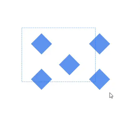
- Selection rectangle/rubber band selection
Clicking and dragging the diagram area allows to create a rectangular region. The elements that are covered under the rectangular region are selected at the end.
Diagram Element Highlighter
The Diagram Element Highlighter feature enhances the selection process by visually distinguishing selected elements and indicating which elements are part of a selection when performing multiple selection actions.
-
Rubber band selection: The first added diagram element will be highlighted with a 2px stroke width, while other selected elements will have a 1px stroke width.
-
Ctrl+Click: The first selected element will have a 2px stroke width, while other selected elements will have a 1px stroke width.
-
Single Selection: The selection highlighter does not apply.
For more information about customizing the Diagram Element Highlighter, refer Customize Highlights for Selected Diagram Elements.
How to Select and Unselect Elements Using Program
Use Select to programmatically select elements and ClearSelection methods help to select or clear the selection of the elements at runtime.
Get the currently selected items from the Nodes and Connectors collection of the SelectionSettings property of the diagram model.
How to Toggle Selection of Elements at Runtime
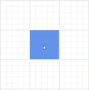
Toggle selection state of diagram elements, including nodes, connectors, groups, and swimlanes, by clicking on them at runtime. The CanToggleSelection property in DiagramSelectionSettings determines whether the selection state of a diagram element should toggle with a mouse click at runtime. By default, this property is set to false.
In the following example, the node can be selected with the first click and unselected with the second click.
@using Syncfusion.Blazor.Diagram

<SfDiagramComponent Height="600px" Nodes="@_nodes" SelectionSettings="@_selectionSettings" />

@code
{
    private DiagramObjectCollection<Node> _nodes;
    private DiagramSelectionSettings _selectionSettings = new DiagramSelectionSettings() { CanToggleSelection = true };

    protected override void OnInitialized()
    {
        _nodes = new DiagramObjectCollection<Node>();
        Node node = new Node()
            {
                ID = "node1",
                OffsetX = 250,
                OffsetY = 250,
                Width = 100,
                Height = 100,
                Style = new ShapeStyle() { Fill = "#6495ED", StrokeColor = "white" }
            };
        _nodes.Add(node);

    }
}A complete working sample can be downloaded from GitHub
How to Select Entire Elements in Diagram Programmatically
The SelectAll method is used to select all the elements such as nodes/connectors in the diagram. Refer to the following link which shows how to use SelectAll method on the diagram.
RubberBand Selection Mode
The RubberBandSelectionMode property in DiagramSelectionSettings controls how elements are selected when using rubber band selection (clicking and dragging to create a rectangular selection area). This property determines which elements get selected based on their intersection with the selection rectangle.
Selection Modes
1. CompleteIntersect Mode
When RubberBandSelectionMode is set to CompleteIntersect:
- Only elements completely covered by the rubber band selection rectangle are selected
- Elements that are partially intersected by the selection rectangle are excluded from selection
- This provides precise selection control, ensuring only fully enclosed elements are selected
2. PartialIntersect Mode
When RubberBandSelectionMode is set to PartialIntersect:
- Elements partially intersected by the rubber band selection are included in the selection
- Any element that touches or overlaps with the selection rectangle, even partially, gets selected
- This provides more flexible selection, making it easier to select multiple elements.
Implementation Example
@page "/"

@using Syncfusion.Blazor.Diagram
@using System.Collections.ObjectModel
@using Syncfusion.Blazor.Buttons

<SfDiagramComponent @ref="_diagram" Width="60%" Height="800px" SelectionSettings="@_select" @bind-Connectors="@_connectors" @bind-Nodes="_nodeCollection"></SfDiagramComponent>
@functions
{

    private string _id = "diagram";
    private SfDiagramComponent _diagram;
    private DiagramObjectCollection<Node> _nodeCollection = new DiagramObjectCollection<Node>();
    private DiagramObjectCollection<Connector> _connectors = new DiagramObjectCollection<Connector>();
    private DiagramSelectionSettings _select;
    protected override void OnInitialized()
    {
        _select = new DiagramSelectionSettings()
         {
            // Set to CompleteIntersect for precise selection
            RubberBandSelectionMode = RubberBandSelectionMode.CompleteIntersect

            // OR set to PartialIntersect for flexible selection
            // RubberBandSelectionMode = RubberBandSelectionMode.PartialIntersect
        };
        Node node1 = new Node()
        {
            ID = "node1",
            OffsetX = 100,
            OffsetY = 100,
            Height = 100,
            Width = 100,
            Annotations = new DiagramObjectCollection<ShapeAnnotation>()
                    {
                        new ShapeAnnotation()
                        {
                            Content = "node1"
                        },
                    },
        };
        _nodeCollection.Add(node1);
        Node node2 = new Node()
        {
            ID = "node2",
            OffsetX = 100,
            OffsetY = 300,
            Height = 100,
            Width = 100,
            Annotations = new DiagramObjectCollection<ShapeAnnotation>()
                    {
                        new ShapeAnnotation()
                        {
                            Content = "node2"
                        },
                    },
        };
        _nodeCollection.Add(node2);
        NodeGroup group1 = new NodeGroup()
        {
            ID = "group1",
            Children = new string[] { "node1", "node2" },
            Annotations = new DiagramObjectCollection<ShapeAnnotation>()
                        {
                            new ShapeAnnotation()
                            {
                            Content = "Group1"
                            }
                        },
        };
        _nodeCollection.Add(group1);
        Node node3 = new Node()
        {
            ID = "node3",
            OffsetX = 300,
            OffsetY = 100,
            Height = 100,
            Width = 100,
            Annotations = new DiagramObjectCollection<ShapeAnnotation>()
                    {
                        new ShapeAnnotation()
                        {
                            Content = "node3"
                        },
                    },
        };
        _nodeCollection.Add(node3);
        Connector connector = new Connector()
        {
            ID = "connector1",
            SourcePoint = new DiagramPoint() { X = 250, Y = 250 },
            TargetPoint = new DiagramPoint() { X = 350, Y = 350 },
        };
        _connectors.Add(connector);
    }
}A complete working sample can be downloaded from GitHub
Getting Current Selected Objects
Access all currently selected elements through the diagram’s SelectionSettings property.
The DiagramSelectionSettings provides access to:
Selected Elements Collections:
- Nodes - Collection of currently selected nodes
- Connectors - Collection of currently selected connectors
- Phases - Collection of currently selected phases (in swimlane diagrams)
- Lanes - Collection of currently selected lanes (in swimlane diagrams)
- Header - Currently selected header (in swimlane diagrams)
- Swimlanes - Collection of currently selected swimlanes
Selection Bounds Properties:
- OffsetX - X-coordinate of the selection bounds center
- OffsetY - Y-coordinate of the selection bounds center
- Width - Total width of the selection bounds
- Height - Total height of the selection bounds
- RotationAngle - Rotation angle of the selection (when multiple elements are selected and rotated together)
- Pivot - Pivot point for rotation operations
@page "/"
@using Syncfusion.Blazor.Diagram
@using Syncfusion.Blazor.Buttons
@using System.Collections.ObjectModel;
@using SelectionChangedEventArgs = Syncfusion.Blazor.Diagram.SelectionChangedEventArgs

<SfButton Content="GetSelectionInfo" OnClick="GetSelectionInfo"></SfButton>
<SfDiagramComponent @ref="_diagram" Height="600px" Nodes="@_nodeCollection" Connectors="@_connectorCollection" SelectionChanged="OnSelectionChanged">
</SfDiagramComponent>
@code {
    private SfDiagramComponent _diagram;
    //Initailize the diagram's nodes collection
    private DiagramObjectCollection<Node> _nodeCollection = new DiagramObjectCollection<Node>();
    //Initailize the diagram's connector collection
    private DiagramObjectCollection<Connector> _connectorCollection = new DiagramObjectCollection<Connector>();
    protected override void OnInitialized()
    {
        Node node1 = new Node()
        {
            OffsetX = 100,
            OffsetY = 200,
            Height = 100,
            Width = 100,
            ID = "node1",
        };
        _nodeCollection.Add(node1);
        Connector connector1 = new Connector()
        {
            ID = "connector1",
            SourcePoint = new DiagramPoint() { X = 300, Y = 100 },
            TargetPoint = new DiagramPoint() { X = 400, Y = 300 },
            Type = ConnectorSegmentType.Orthogonal
        };
        _connectorCollection.Add(connector1);
    }
    //Event to notify selection changing event after selected the nodes/conenctors in diagram.
    private void OnSelectionChanged(SelectionChangedEventArgs args)
    {
        if (_diagram.SelectionSettings.Nodes.Count > 0)
        {
            Node selectedNode = _diagram.SelectionSettings.Nodes[0];
            //Here you can modified the selected node.
        }
        if (_diagram.SelectionSettings.Connectors.Count > 0)
        {
            Connector selectedConnector = _diagram.SelectionSettings.Connectors[0];
            //Here you can modified the selected connector.
        }
    }

    // Method to get current selection information
    private void GetSelectionInfo()
    {
        // Get selected nodes
        ObservableCollection<Node> selectedNodes = _diagram.SelectionSettings.Nodes;
        foreach (Node node in selectedNodes)
        {
            Console.WriteLine($"Selected Node ID: {node.ID}");
            Console.WriteLine($"Node OffsetX: {node.OffsetX}");
            Console.WriteLine($"Node OffsetY: {node.OffsetY}");
            Console.WriteLine($"Node Width: {node.Width}");
            Console.WriteLine($"Node Height: {node.Height}");
            Console.WriteLine($"Node Rotation: {node.RotationAngle}");
        }

        // Get selected connectors
        ObservableCollection<Connector> selectedConnectors = _diagram.SelectionSettings.Connectors;
        foreach (Connector connector in selectedConnectors)
        {
            Console.WriteLine($"Selected Connector ID: {connector.ID}");
            Console.WriteLine($"Connector SourcePoint: X={connector.SourcePoint.X}, Y={connector.SourcePoint.Y}");
            Console.WriteLine($"Connector TargetPoint: X={connector.TargetPoint.X}, Y={connector.TargetPoint.Y}");
        }

        // Get selection bounds information
        Console.WriteLine($"Selection OffsetX: {_diagram.SelectionSettings.OffsetX}");
        Console.WriteLine($"Selection OffsetY: {_diagram.SelectionSettings.OffsetY}");
        Console.WriteLine($"Selection Width: {_diagram.SelectionSettings.Width}");
        Console.WriteLine($"Selection Height: {_diagram.SelectionSettings.Height}");
        Console.WriteLine($"Selection Rotation: {_diagram.SelectionSettings.RotationAngle}");
        Console.WriteLine($"Selection Pivot: {_diagram.SelectionSettings.Pivot}");
    }
}A complete working sample can be downloaded from GitHub
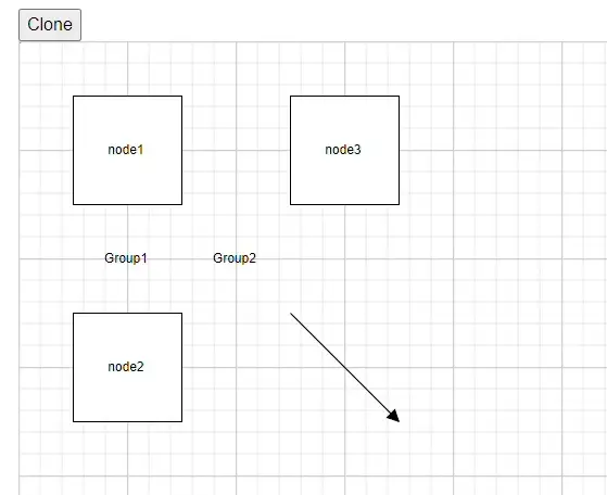
How to clone the selected nodes and connector at runtime
Clone is a virtual method of the node used to create a copy of a diagram object. After cloning, it is necessary to set a unique ID for the cloned nodes and connectors. The following code demonstrates how to clone selected nodes during runtime.
@using Syncfusion.Blazor.Diagram
@using System.Collections.ObjectModel
@inject IJSRuntime js
@using Syncfusion.Blazor.Buttons


<SfButton Content="Clone" OnClick="@Clone" />
<SfDiagramComponent @ref="_diagram" Width="60%" Height="800px" @bind-Connectors="@_connectors" @bind-Nodes="_nodeCollection"></SfDiagramComponent>
@functions
{
    private string _id = "diagram";
    private SfDiagramComponent _diagram;
    private DiagramObjectCollection<Node> _nodeCollection = new DiagramObjectCollection<Node>();
    private DiagramObjectCollection<Connector> _connectors = new DiagramObjectCollection<Connector>();
    protected override void OnInitialized()
    {
        Node node1 = new Node()
            {
                ID = "node1",
                OffsetX = 100,
                OffsetY = 100,
                Height = 100,
                Width = 100,
                Annotations = new DiagramObjectCollection<ShapeAnnotation>()
                    {
                        new ShapeAnnotation()
                        {
                            Content = "node1"
                        },
                    },
            };
        _nodeCollection.Add(node1);
        Node node2 = new Node()
            {
                ID = "node2",
                OffsetX = 100,
                OffsetY = 300,
                Height = 100,
                Width = 100,
                Annotations = new DiagramObjectCollection<ShapeAnnotation>()
                    {
                        new ShapeAnnotation()
                        {
                            Content = "node2"
                        },
                    },
            };
        _nodeCollection.Add(node2);
        NodeGroup group1 = new NodeGroup()
            {
                ID = "group1",
                Children = new string[] { "node1", "node2" },
                Annotations = new DiagramObjectCollection<ShapeAnnotation>()
                        {
                            new ShapeAnnotation()
                            {
                            Content = "Group1"
                            }
                        },
            };
        _nodeCollection.Add(group1);
        Node node3 = new Node()
            {
                ID = "node3",
                OffsetX = 300,
                OffsetY = 100,
                Height = 100,
                Width = 100,
                Annotations = new DiagramObjectCollection<ShapeAnnotation>()
                    {
                        new ShapeAnnotation()
                        {
                            Content = "node3"
                        },
                    },
            };
        _nodeCollection.Add(node3);
        Connector connector = new Connector()
            {
                ID = "connector1",
                SourcePoint = new DiagramPoint() { X = 250, Y = 250 },
                TargetPoint = new DiagramPoint() { X = 350, Y = 350 },
            };
        _connectors.Add(connector);
        NodeGroup group2 = new NodeGroup()
            {
                ID = "group2",
                Children = new string[] { "node3", "connector1", "group1" },
                Annotations = new DiagramObjectCollection<ShapeAnnotation>()
                        {
                            new ShapeAnnotation()
                            {
                            Content = "Group2"
                            }
                        },
            };
        _nodeCollection.Add(group2);
    }
    private void Clone()
    {
        _diagram.StartGroupAction();
        if (_diagram.SelectionSettings.Nodes.Count > 0)
        {
            NodeBase NodeObj = _diagram.SelectionSettings.Nodes[0] as NodeBase;
            if (NodeObj is NodeGroup gNode)
            {
                CloneGroup(gNode, false);
            }
            else if (NodeObj is Node node)
            {
                CloneNode(node, false);
            }
        }
        if (_diagram.SelectionSettings.Connectors.Count > 0)
        {
            NodeBase ConnectorObj = _diagram.SelectionSettings.Connectors[0] as NodeBase;
            if (ConnectorObj is Connector connectorObj)
            {
                CloneConnector(connectorObj, false);
            }
        }
        _diagram.ClearSelection();
        _diagram.EndGroupAction();
    }
    private string CloneGroup(NodeGroup gNode, bool isChild)
    {
        NodeGroup groupNode = gNode.Clone() as NodeGroup;
        groupNode.ID = RandomId();
        List<string> child = new List<string>();
        foreach (string childID in groupNode.Children)
        {
            for (int i = 0; i < _diagram.Nodes.Count; i++)
            {
                if (childID == _diagram.Nodes[i].ID && _diagram.Nodes[i] is NodeGroup nodeGroup)
                {
                    child.Add(CloneGroup(nodeGroup, true));
                }
                else if (childID == _diagram.Nodes[i].ID)
                {
                    child.Add(CloneNode(_diagram.Nodes[i], true));
                }
            }
            for (int i = 0; i < _diagram.Connectors.Count; i++)
            {
                if (childID == _diagram.Connectors[i].ID)
                {
                    child.Add(CloneConnector(_diagram.Connectors[i], true));
                }
            }
        }
        groupNode.Children = child.ToArray();
        if (!isChild)
        {
            groupNode.OffsetX += 25;
            groupNode.OffsetY += 25;
        }
        _diagram.AddDiagramElementsAsync(new DiagramObjectCollection<NodeBase>() { groupNode });
        return groupNode.ID;
    }
    private string CloneNode(Node node, bool isChild)
    {
        _diagram.StartGroupAction();
        Node nodeChild = node.Clone() as Node;
        nodeChild.ID = RandomId();
        if (!isChild)
        {
            nodeChild.OffsetX += 25;
            nodeChild.OffsetY += 25;
        }
        _diagram.AddDiagramElementsAsync(new DiagramObjectCollection<NodeBase>() { nodeChild });
        _diagram.EndGroupAction();
        return nodeChild.ID;
    }
    private string CloneConnector(Connector connector, bool isChild)
    {
        _diagram.StartGroupAction();
        Connector connectorChild = connector.Clone() as Connector;
        connectorChild.ID = RandomId();
        if (!isChild)
        {
            connectorChild.SourcePoint = new DiagramPoint() { X = connectorChild.SourcePoint.X + 25, Y = connectorChild.SourcePoint.Y + 25 };
            connectorChild.TargetPoint = new DiagramPoint() { X = connectorChild.TargetPoint.X + 25, Y = connectorChild.TargetPoint.Y + 25 };
        }
        _diagram.AddDiagramElementsAsync(new DiagramObjectCollection<NodeBase>() { connectorChild });
        _diagram.EndGroupAction();
        return connectorChild.ID;
    }
    private string RandomId()
    {
        Random random = new Random();
        const string chars = "ABCDEFGHIJKLMNOPQRSTUVWXTZabcdefghiklmnopqrstuvwxyz";
#pragma warning disable CA5394 // Do not use insecure randomness
        return new string(Enumerable.Repeat(chars, 5)
          .Select(s => s[random.Next(s.Length)]).ToArray());
#pragma warning restore CA5394 // Do not use insecure randomness
    }
}A complete working sample can be downloaded from GitHub
How to Access and Modify Selected Nodes and Connectors at Runtime
Access and update the properties of selected nodes and connectors using the SelectionSettings API in Blazor’s SfDiagramComponent. This allows to respond to user selections and dynamically modify diagram elements at runtime. The following code demonstrates how to access and modify the selected Node and selected connector during runtime.
@page "/"
@using Syncfusion.Blazor.Diagram

<SfDiagramComponent @ref="_diagram" Height="600px" Nodes="@_nodeCollection" Connectors="@_connectorCollection"
SelectionChanged="OnSelectionChanged">
</SfDiagramComponent>
@code {
    private SfDiagramComponent _diagram;
    //Initailize the diagram's nodes collection
    private DiagramObjectCollection<Node> _nodeCollection = new DiagramObjectCollection<Node>();
    //Initailize the diagram's connector collection
    private DiagramObjectCollection<Connector> _connectorCollection = new DiagramObjectCollection<Connector>();
    protected override void OnInitialized()
    {
        Node node1 = new Node()
            {
                OffsetX = 100,
                OffsetY = 200,
                Height = 100,
                Width = 100,
                ID = "node1",
            };
        _nodeCollection.Add(node1);
        Connector connector1 = new Connector()
            {
                ID = "connector1",
                SourcePoint = new DiagramPoint() { X = 300, Y = 100 },
                TargetPoint = new DiagramPoint() { X = 400, Y = 300 },
                Type = ConnectorSegmentType.Orthogonal
            };
        _connectorCollection.Add(connector1);
    }
    //Event to notify selection changing event after selected the nodes/conenctors in diagram.
    private void OnSelectionChanged(SelectionChangedEventArgs args)
    {
        if (_diagram.SelectionSettings.Nodes.Count > 0)
        {
            Node selectedNode = _diagram.SelectionSettings.Nodes[0];
            //Here you can modified the selected node.
        }
        if (_diagram.SelectionSettings.Connectors.Count > 0)
        {
            Connector selectedConnector = _diagram.SelectionSettings.Connectors[0];
            //Here you can modified the selected connector.
        }
    }
}
A complete working sample can be downloaded from GitHub
How to Drag Elements
- An object can be dragged by clicking and dragging it. When multiple elements are selected, dragging any one of the selected elements moves every selected element.
- When you drag the elements in the diagram, the following events are triggered and do customization on those events.
| Events | EventArgs | Description |
|---|---|---|
| PositionChanging | PositionChangingEventArgs | Notify while dragging the elements in the diagram. |
| PositionChanged | PositionChangedEventArgs | Notify when the element’s position has changed in the diagram. |
@using Syncfusion.Blazor.Diagram

<SfDiagramComponent Height="600px" Nodes="@_nodeCollection"
    PositionChanging="OnPositionChanging"
    PositionChanged="OnPositionChanged">
</SfDiagramComponent>
@code
{
    private DiagramObjectCollection<Node> _nodeCollection = new DiagramObjectCollection<Node>();
    protected override void OnInitialized()
    {
        Node node = new Node()
        {
            OffsetX = 100,
            OffsetY = 200,
            Height = 100,
            Width = 100,
            ID = "node",
        };
        _nodeCollection.Add(node);
    }
    //Event to notify while dragging the elements in the diagram.
    private void OnPositionChanging(PositionChangingEventArgs args)
    {
        //sets true to cancel the element's dragging
        args.Cancel = true;
    }
    //Event to notify once element's position has changed in the diagram.
    private void OnPositionChanged(PositionChangedEventArgs args)
    {
        //Action to be performed.
    }
}A complete working sample can be downloaded from GitHub
For more information about dragging, refer Node Drag
How to Resize Elements
- The selector is surrounded by eight thumbs. When dragging these thumbs, selected items can be resized.
- When one corner of the selector is dragged, the opposite corner remains in a static position.
- When a node is resized, the following events get triggered.
| Events | EventArgs | Description |
|---|---|---|
| SizeChanging | SizeChangingEventArgs | Notify while resizing the elements in the diagram. |
| SizeChanged | SizeChangedEventArgs | Notify when the element’s size has changed in the diagram. |
@using Syncfusion.Blazor.Diagram

<SfDiagramComponent Height="600px" Nodes="@_nodeCollection"
    SizeChanging="OnSizeChanging"
    SizeChanged="OnSizeChanged">
</SfDiagramComponent>

@code
{
    private DiagramObjectCollection<Node> _nodeCollection = new DiagramObjectCollection<Node>();
    protected override void OnInitialized()
    {
        Node node = new Node()
        {
            OffsetX = 100,
            OffsetY = 200,
            Height = 100,
            Width = 100,
            ID = "node",
        };
        _nodeCollection.Add(node);
    }
    //Event to notify while resizing the elements in the diagram.
    private void OnSizeChanging(SizeChangingEventArgs args)
    {
        //sets true to cancel the element's resizing
        args.Cancel = true;
    }
    //Event to notify once element's size has changed in the diagram.
    private void OnSizeChanged(SizeChangedEventArgs args)
    {
        //Action to be performed.
    }
}A complete working sample can be downloaded from GitHub
For more information about resizing, refer Node Resize
NOTE
While dragging and resizing, the objects are snapped towards the nearest objects to make better alignments. For better alignments, refer to Snapping.
How to Rotate Elements
- A rotate handler is placed above the selector. Clicking and dragging the handler in a circular direction lead to rotate the node.
- The node is rotated with reference to the static pivot point.
- A pivot thumb (thumb at the middle of the node) appears while rotating the node to represent the static point.
- When a node is rotated, the following events get triggered.
| Events | EventArgs | Description |
|---|---|---|
| RotationChanging | RotationChangingEventArgs | Notify while rotating the elements in the diagram. |
| RotationChanged | RotationChangedEventArgs | Notify when the element’s rotate angle has changed in the diagram. |
@using Syncfusion.Blazor.Diagram

<SfDiagramComponent Height="600px" Nodes="@_nodeCollection"
    RotationChanging="OnRotationChanging"
    RotationChanged="OnRotationChanged">
</SfDiagramComponent>

@code
{
    private DiagramObjectCollection<Node> _nodeCollection = new DiagramObjectCollection<Node>();
    protected override void OnInitialized()
    {
        Node node = new Node()
        {
            OffsetX = 100,
            OffsetY = 200,
            Height = 100,
            Width = 100,
            ID = "node",
        };
        _nodeCollection.Add(node);
    }
    //Event to notify while rotating the elements in the diagram.
    private void OnRotationChanging(RotationChangingEventArgs args)
    {
        //sets true to cancel the element's rotation
        args.Cancel = true;
    }
    //Event to notify once element's rotate angle has changed in the diagram.
    private void OnRotationChanged(RotationChangedEventArgs args)
    {
        //Action to be performed.
    }
}A complete working sample can be downloaded from GitHub
For more information about resizing, refer Node Rotate
How to Edit Connector Segments
- Each segment of a selected connector is editable with some specific handles/thumbs.
How to Adjust Connector End Point Handles
Source and target points of the selected connectors are represented by two handles. Clicking and dragging those handles helps to adjust the source and target points.
For more information, refer End Point Dragging
- Drag the connector end points, then the following events can be used to do your customization.
- Connect connector with ports or node or disconnect from it, the following events are triggered.
| Events | EventArgs | Description |
|---|---|---|
| ConnectionChanging | ConnectionChangingEventArgs | Notify while creating the connection between the nodes in the diagram. |
| ConnectionChanged | ConnectionChangedEventArgs | Notify once the connection has been created between the nodes in the diagram. |
@using Syncfusion.Blazor.Diagram

<SfDiagramComponent Height="600px" Nodes="@_nodeCollection" Connectors="@_connectorCollection"
    ConnectionChanging="OnConnectionChanging"
    ConnectionChanged="OnConnectionChanged">
</SfDiagramComponent>

@code
{
    private DiagramObjectCollection<Node> _nodeCollection = new DiagramObjectCollection<Node>();
    private DiagramObjectCollection<Connector> _connectorCollection = new DiagramObjectCollection<Connector>();
    protected override void OnInitialized()
    {
        Node node1 = new Node()
        {
            OffsetX = 100,
            OffsetY = 200,
            Height = 100,
            Width = 100,
            ID = "node1",
        };
        _nodeCollection.Add(node1);

        Node node2 = new Node()
        {
            OffsetX = 300,
            OffsetY = 200,
            Height = 100,
            Width = 100,
            ID = "node2",
        };
        _nodeCollection.Add(node2);

        Connector connector = new Connector()
        {
            ID = "connector1",
            //Source node id of the connector.
            SourceID = "node1",
            TargetDecorator = new DecoratorSettings()
            {
                Style = new ShapeStyle()
                {
                    Fill = "#6495ED",
                    StrokeColor = "#6495ED",
                }
            },
            //Target node id of the connector.
            TargetID = "node2",
            Style = new ShapeStyle()
            {
                Fill = "#6495ED",
                StrokeColor = "#6495ED",
            },
            // Type of the connector.
            Type = ConnectorSegmentType.Straight,
        };
        _connectorCollection.Add(connector);
    }
    //Event to notify while creating the connection between the nodes in the diagram.
    private void OnConnectionChanging(ConnectionChangingEventArgs args)
    {
        //Sets true to cancel the element's resizing.
        args.Cancel = true;
    }
    //Event to notify once created the connection between the nodes in the diagram.
    private void OnConnectionChanged(ConnectionChangedEventArgs args)
    {
        //Action to be performed.
    }
}A complete working sample can be downloaded from GitHub
How to Edit Straight Connector Segments
- End point of each straight segment is represented by a thumb that enables to edit the segment.
- Any number of new segments can be inserted into a straight line by clicking, when Shift and Ctrl keys are pressed (Ctrl+Shift+Click).
- Straight segments can be removed by clicking the segment end point, when Ctrl and Shift keys are pressed (Ctrl+Shift+Click).
For more information about straight segment editing, refer Straight Segment Editing
How to Edit Orthogonal Connector Segments
- Orthogonal thumbs allow you to adjust the length of adjacent segments by clicking and dragging them.
- When necessary, some segments are added or removed automatically, when dragging the segment. This is to maintain proper routing of orthogonality between segments.
- When editing the segment collection of a connector, the following event gets triggered.
| Events | EventArgs | Description |
|---|---|---|
| SegmentCollectionChange | SegmentCollectionChangeEventArgs | Notify when the connector’s segment collection has modified in the diagram. |
@using Syncfusion.Blazor.Diagram

<SfDiagramComponent Width="1000px" Height="500px" Connectors="@_connectors" SegmentCollectionChange="OnSegmentChange">
</SfDiagramComponent>
@code{
    //Defines diagram's connector collection.
    private DiagramObjectCollection<Connector> _connectors = new DiagramObjectCollection<Connector>();
    protected override void OnInitialized()
    {

        Connector connector = new Connector()
        {
            ID = "connector1",
            SourcePoint = new DiagramPoint()
            {
                X = 100,
                Y = 100
            },
            // Enable DragSegmentThumb constraints to segment editing.
            Constraints = ConnectorConstraints.Default | ConnectorConstraints.DragSegmentThumb,
            Style = new ShapeStyle() { StrokeColor = "#6f409f", StrokeWidth = 1 },
            TargetPoint = new DiagramPoint() { X = 300, Y = 300 },
             //Specify the segments type as Orthogonal.
            Type = ConnectorSegmentType.Orthogonal,
             //Create a new segment with length and direction.
            Segments = new DiagramObjectCollection<ConnectorSegment>()
            {
                new OrthogonalSegment
                {
                    Length = 100,
                    Type = ConnectorSegmentType.Orthogonal,
                    Direction = Direction.Right,
                },
                new OrthogonalSegment
                {
                    Length = 100,
                    Type = ConnectorSegmentType.Orthogonal,
                    Direction = Direction.Bottom,
                }
            },
            TargetDecorator = new DecoratorSettings()
            {
                Shape = DecoratorShape.Arrow,
                Style = new ShapeStyle()
                {
                    Fill = "#6f409f",
                    StrokeColor = "#6f409f",
                    StrokeWidth = 1
                }
            }

        };
        _connectors.Add(connector);
    }
    //Event to notify while modifying the segment collection for the connector.
    private void OnSegmentChange(SegmentCollectionChangeEventArgs args)
    {
        //Action to be performed.
    }
}A complete working sample can be downloaded from GitHub
For more information about orthogonal segment editing, refer Orthogonal Segment Editing.
How to Create User Handles
- User handles are used to add some frequently used commands around the selector. To create user handles, define and add them to the UserHandles collection of the SelectionSettings property.
- The Name property of user handle is used to define the name of the user handle and it is further used to find the user handle at runtime and do any customization.
How to Align User Handle Based on Node Boundary
User handles can be aligned relative to the node boundaries. It has Margin, Offset, Side, HorizontalAlignment, and VerticalAlignment settings. It is quite tricky when all four alignments are used together, but gives more control over alignment.
How to Position User Handle
The Offset property of a UserHandle is used to align the user handle based on fractions. 0 represents top or left corner, 1 represents bottom or right corner, and 0.5 represents half of width or height.
HHow to Align User Handles Based on Connector Boundary
The Side property of a UserHandle is used to align the user handle by using the Top, Bottom, Left, and Right options.
How to Add Horizontal and Vertical Alignment to User Handle
The HorizontalAlignment property of a UserHandle is used to set how the user handle is horizontally aligned at the position based on the Offset. The VerticalAlignment property is used to set how user handle is vertically aligned at the position.
How to Add Margin to User Handle
Margin is an absolute value used to add some blank space on any one of its four sides. The UserHandle can be displaced with the Margin property.
How to Receive Mouse Button Click Notifications
The diagram component notifies the mouse button clicked. For example, whenever the right mouse button is clicked, the clicked button is notified as right. The mouse click is notified with,
| Notification | Description |
|---|---|
| Left | When the left mouse button is clicked, left is notified |
| Middle | When the mouse wheel is clicked, middle is notified |
| Right | When the right mouse button is clicked, right is notified |
@using Syncfusion.Blazor.Diagram

<SfDiagramComponent Height="600px" Nodes="@_nodes" Click='@OnClick' />

@code
{
    private DiagramObjectCollection<Node> _nodes = new DiagramObjectCollection<Node>();
    protected override void OnInitialized()
    {
        _nodes = new DiagramObjectCollection<Node>();
        // A node is created and stored in nodes array.
        Node node = new Node()
        {
            // Position of the node.
            OffsetX = 250,
            OffsetY = 250,
            // Size of the node.
            Width = 100,
            Height = 100,
            // Add node.
            Style = new ShapeStyle() { Fill = "#6BA5D7", StrokeDashArray = "5,5", StrokeColor = "red", StrokeWidth = 2 },
        };
        _nodes.Add(node);
    }

    private void OnClick(ClickEventArgs args)
    {
        Console.WriteLine("Button", args.Button);
    }
}A complete working sample can be downloaded from GitHub
How to Customize the Appearance of User Handle
The appearance of the user handle can be customized using the Size, BorderColor, BackgroundColor, Visible, PathData, and PathColor properties of the UserHandle.
How to Zoom and Pan the Diagram
- When a large diagram is loaded, only certain portion of the diagram is visible. The remaining portions are clipped. Clipped portions can be explored by scrolling the scrollbars or panning the diagram.
- The diagram can be zoomed in or out by using Ctrl + mouse wheel.
Keyboard Shortcuts and Navigation
Diagram provides support to interact with elements with key gestures. By default, some in-built commands are bound with a relevant set of key combinations.
The following table illustrates those commands with the associated key values.
| Shortcut Key | Command | Description |
|---|---|---|
| Ctrl + A | SelectAll | Select all nodes/connectors in the diagram. |
| Ctrl + Plus | ZoomIn | Zoom in the diagram. |
| Ctrl + Minus | ZoomOut | Zoom out the diagram. |
| Ctrl + C | Copy | Copy the diagram selected elements. |
| Ctrl + V | Paste | Pastes the copied elements. |
| Ctrl + X | Cut | Cuts the selected elements. |
| Ctrl + Z | Undo | Reverses the last editing action performed on the diagram. |
| Ctrl + Y | Redo | Restores the last editing action when no other actions have occurred since the last undo on the diagram. |
| Delete | Delete | Deletes the selected elements. |
| Ctrl/Shift + Click on object | Multiple selection (Selector binds all selected nodes/connectors). | |
| Up Arrow | Nudge(Direction.Up) |
NudgeUp: Moves the selected elements towards up by one pixel. |
| Down Arrow | Nudge(Direction.Down) |
NudgeDown: Moves the selected elements towards down by one pixel. |
| Left Arrow | Nudge(Direction.Left) |
NudgeLeft: Moves the selected elements towards left by one pixel. |
| Right Arrow | Nudge(Direction.Right) |
NudgeRight: Moves the selected elements towards right by one pixel. |
| Ctrl + MouseWheel | Zoom | Zoom (Zoom in/Zoom out the diagram). |
| F2 | StartTextEdit | Starts to edit the label of selected element. |
| Esc | Sets the label mode as view and stops editing. |
See Also
-
How to Get the Mouse Position When Hovering Over the Diagram Area in Blazor Diagram
-
How to Drag a Node Programmatically Without User Interaction in Blazor Diagram
-
How to Add Nodes and Connectors at Runtime Asynchronously in Blazor Diagram Component
-
How to Identify the Clicked Diagram Elements in Blazor Diagram
-
How to Add Nodes or Connectors by Clicking on the Diagram in Blazor Diagram Component
-
How to Disable Node Interaction While Maintaining Layout Updates in Blazor Diagram
-
How to Make HTML Node Resizable but Not Draggable in Blazor Diagram
-
How to Drag and Drop of Listbox Element into Blazor Diagram Control
-
How to Customize the Appearance of the Selector in Blazor Diagram
-
How to Make Nodes Read-Only Except for Selection in Blazor Diagram